はじめに
Here's a step-by-step tutorial to dismount each piece of the NAS until you reach the motherboard.
'Note: the interest of this tutorial is however limited.'
Indeed, most of the components that a user can be brought to add or change are now accessible directly, without disassembly (storage disks, memory expansion, SSD cache).
This is a step forward since, for example, a DS415 + / DS916 + must be completely removed to change a single RAM array.
Only the memory stack on the motherboard and fans remain inaccessible directly and require the disassembly of the NAS described in this tutorial to be changed (whether they are HS or replace them not the best).
The dismantling time is estimated at one hour (a single experiment on the timer). That said, it is certainly achievable in 20/30 minutes.
The photographs were taken with a CANON EOS 7D and an iPhone SE, using a portable LED studio.
必要な工具と部品
-
-
Here are the different interesting faces of the case: front (bay disks), rear (connectors and fans), below (2 hatches SSD).
-
2 RJ45 Gb ports.
-
Kensington security incision (K-lock)
-
2 M.2 NVMe 2280 ports (disk cache)
-
1 port for power supply
-
2 USB 3 ports (1 in front and 1 behind)
-
1 eSATA port
-
-
-
This is a significant innovation, the memory is now directly accessible and without disassembly of the housing, for the original bar as for the extension port.
-
-
-
Remove the 2 screws on the back of the case at the top and bottom (not the one above the USB port)
-
-
-
in red: SSD M.2 expansion card 2280
-
in yellow: USB port 3
-
in orange: internal connectors of the 2 fans
-
in green: 2 slots of RAM
-
in blue: SATA III backplane (4 hard drive bays)
-
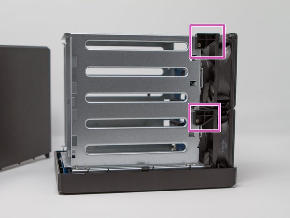
in pink: fixing the fans on the chassis
-
-
-
-
Remove the 4 screws located on the blue electronic board.
-
You can remove the M.2 expansion board now.
-
-
-
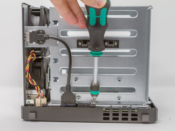
Remove the screw from the holding plate of the USB connector 3.
-
Also remove the USB 3 connector screw on the rear side (this can be done later).
-
-
-
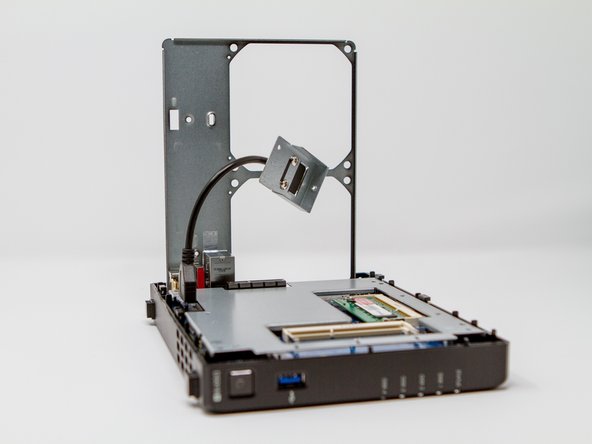
Remove the screws from the two shims to secure the disc cage and the two fans.
-
-
-
First 3 screws on SSD expansion board, on the bottom (bottom).
-
-
-
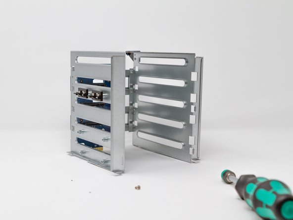
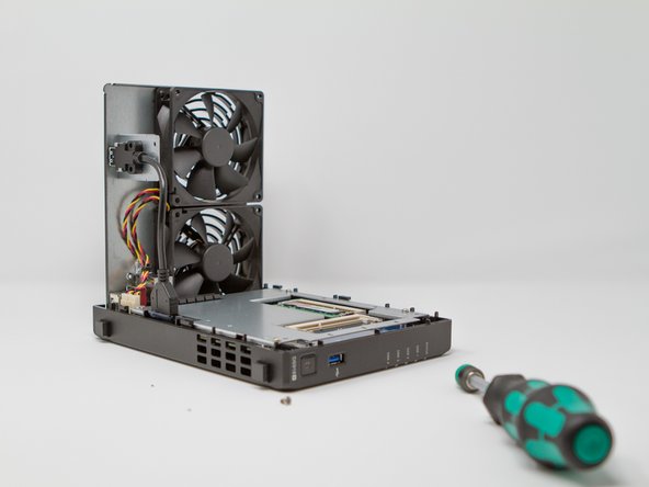
Now that the screws have been removed, you can (after verification) remove the cage drives.
-
-
-
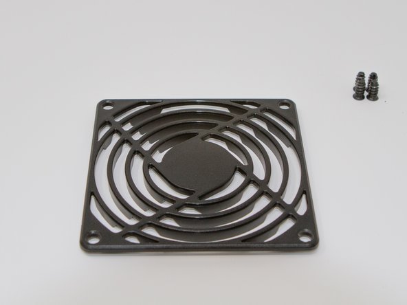
Remove the 8 screws from the fan grilles. They make it possible to maintain both the grilles and the fans.
-
-
-
According to the technical documentation of Y.S. TECH:
-
Voltage: 12 Vdc (7 to 13.2 range) for 100 mA (consumption)
-
Life time @ 40 ° C L10: 50000 h
-
Noise level: 23 dB
-
Max airflow: 36.3 cubic feet / minute
-
Rotation speed: 1900 rpm
-
Weight: 100 g
-
-
-
Remove the power cables from the fans, being careful to locate them (you never know) located on the motherboard.
-
Then remove the fans.
-
You will also be careful to unscrew the USB 3 connector fixing screw on the rear panel (if this has not been done previously).
-
-
-
Remove the 4 screws that secure the motherboard to the case.
-
Remove the motherboard from the case paying attention to the USB 3 connector on the front and the power button. To do this, move the front panel a little and lift the motherboard upwards (outside).
-
Once the motherboard is out, unscrew the 4 screws of the metal protective cover (metal plate).
-
-
-
Motherboard processor face
-
INTEL Celeron J3455 / 64-bit / Quad core 1.5 burst up to 2.3 GHz
-
Memory battery
-
Internal Beep
-
USB connector 3
-
Power button (power-on)
-
Flash memory with pre-loaded DSM 6.1 kernel to allow the NAS to boot before full installation of the OS
-
UEFI Insyde H2O BY56 chip ??
-
-
-
Memory side of the motherboard (pre-equipped with 4 GB of RAM)
-
NVMe M.2 SSD expansion card connector
-
Connector (PCIe ??) for SATA disk expansion card
-
Fan connector (x2)
-
Power connector
-
RJ45 LAN Connector (8P8C) x2
-
ESATA connector
-
Original 4GB DDR3L RAM Memory Stick 1866
-
To reassemble your device, follow the instructions in reverse order.
Be careful however, for the grilles of the fans it will be necessary to make sure to align the 2 small raised lugs on the back of the plastic grilles with the 2 small holes between the screws of the bottom of the fans!
To reassemble your device, follow the instructions in reverse order.
Be careful however, for the grilles of the fans it will be necessary to make sure to align the 2 small raised lugs on the back of the plastic grilles with the 2 small holes between the screws of the bottom of the fans!
36 の人々がこのガイドを完成させました。
以下の翻訳者の皆さんにお礼を申し上げます:
100%
これらの翻訳者の方々は世界を修理する私たちのサポートをしてくれています。 あなたも貢献してみませんか?
翻訳を始める ›
15 件のコメント
Un tutoriel complet, avec de bonnes photos, lecture claire et concise.
Bravo et merci pour ton travail.
merci pour ces encouragements !


