メインコンテンツにスキップ

RCA RP3715A Motherboard Replacement

必要な工具と部品

  1. RCA RP3715A Motherboard Replacement, Getting inside the device.: 手順 1、 1の画像 1
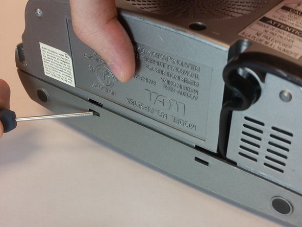
    • Take out the six screws located on the back of the device.

    • The red screws are 10 mm Phillip's #1. The orange screws are 13 mm Phillips #1.

    • Three screws are located on the back panel. One is located inside the battery carriage.

    • Two screws are located on the on the back panel on the bottom left and right side.

  2. RCA RP3715A Motherboard Replacement, Relieve extension cord tension.: 手順 2、 3の画像 1 RCA RP3715A Motherboard Replacement, Relieve extension cord tension.: 手順 2、 3の画像 2 RCA RP3715A Motherboard Replacement, Relieve extension cord tension.: 手順 2、 3の画像 3
    • Remove the 10 mm Phillip's #1 screw.

    • Then remove the metal reinforcement.

  3. RCA RP3715A Motherboard Replacement: 手順 3、 2の画像 1 RCA RP3715A Motherboard Replacement: 手順 3、 2の画像 2
    • Using flathead screwdriver undo the release tabs.

  4. RCA RP3715A Motherboard Replacement: 手順 4、 3の画像 1 RCA RP3715A Motherboard Replacement: 手順 4、 3の画像 2 RCA RP3715A Motherboard Replacement: 手順 4、 3の画像 3
    • Pry the release tabs with a spudger.

    • Start with back of the device on the topside.

  5. RCA RP3715A Motherboard Replacement: 手順 5、 2の画像 1 RCA RP3715A Motherboard Replacement: 手順 5、 2の画像 2
    • Pry open both tabs to remove the topside of the clock.

  6. RCA RP3715A Motherboard Replacement, Speaker Replacement: 手順 6、 1の画像 1
    • Remove the two 10mm Phillip's #1 screws. Also remove the two reinforcements holding the speaker in place.

  7. RCA RP3715A Motherboard Replacement, Detaching the front panel: 手順 7、 1の画像 1
    • Remove the two 10 mm Phillip's #1 screws.

  8. RCA RP3715A Motherboard Replacement: 手順 8、 1の画像 1
    • Remove the gray panel from the frame.

  9. RCA RP3715A Motherboard Replacement, Unlatch release tabs: 手順 9、 3の画像 1 RCA RP3715A Motherboard Replacement, Unlatch release tabs: 手順 9、 3の画像 2 RCA RP3715A Motherboard Replacement, Unlatch release tabs: 手順 9、 3の画像 3
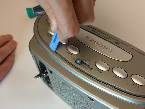
    • The two latches located in the picture will help take off the display.
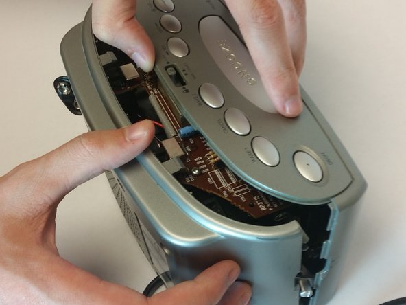
    • Remove the display.

  10. RCA RP3715A Motherboard Replacement, Motherboard: 手順 10、 2の画像 1 RCA RP3715A Motherboard Replacement, Motherboard: 手順 10、 2の画像 2
    • asd

  11. RCA RP3715A Motherboard Replacement, Removing the top part of motherboard: 手順 11、 1の画像 1
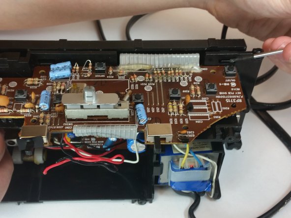
    • Remove the top 5 10mm Phillips #1 screws holding the top part of the motherboard

  12. RCA RP3715A Motherboard Replacement, Removing the side part of motherboard: 手順 12、 1の画像 1
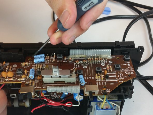
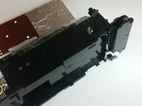
    • Remove the 5 10mm Phillip's #1 screws that holding side part of the motherboard

  13. RCA RP3715A Motherboard Replacement: 手順 13、 1の画像 1
    • Remove the transformer by pulling back the release tab shown.

  14. RCA RP3715A Motherboard Replacement: 手順 14、 1の画像 1
    • Pull the battery terminal through the whole shown.

  15. RCA RP3715A Motherboard Replacement, Lift the digital screen: 手順 15、 1の画像 1
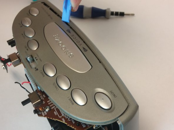
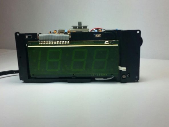
    • First release the latch highlighted in the picture. Then grab the screen by the bottom and lift it up.

  16. RCA RP3715A Motherboard Replacement, Lift the top piece of motherboard: 手順 16、 3の画像 1 RCA RP3715A Motherboard Replacement, Lift the top piece of motherboard: 手順 16、 3の画像 2 RCA RP3715A Motherboard Replacement, Lift the top piece of motherboard: 手順 16、 3の画像 3
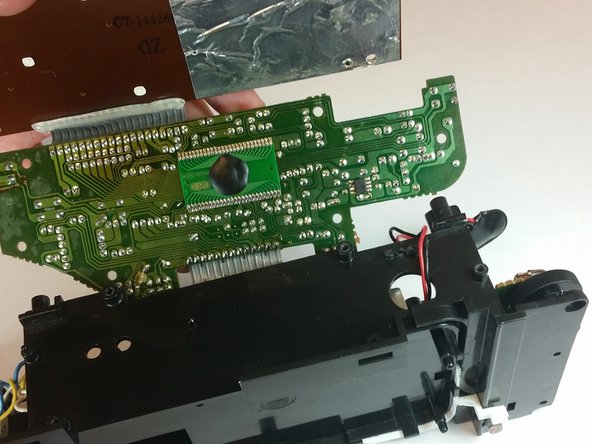
    • Remove the motherboard from the frame using the illustration shown.

終わりに

To reassemble your device, follow these instructions in reverse order.

ある他の人がこのガイドを完成しました。

作成者

3人の作成者と共同で作成されました。

Alexander Trowell

メンバー登録日: 09/22/14

222 ポイント

2のガイドは作成済み

チーム

USF Tampa, Team 10-5, Brown Fall 2014 USF Tampa, Team 10-5, Brown Fall 2014人のメンバー

USFT-BROWN-F14S10G5

3 メンバー

5のガイドは作成済み

0 件のコメント

コメントを追加

統計データ:

過去 24時間: 0

過去 7 日: 0

過去 30 日: 4

今までの合計 546