メインコンテンツにスキップ

Quantum View 10.1 Keyboard connector solid state board Replacement

必要な工具と部品

  1. Quantum View 10.1 Keyboard connector solid state board Replacement, Open Quantum View case: 手順 1、 1の画像 1
    • Start by turning the tablet over with the screen down. Carefully use a plastic opening tool to pry the cover off. Start from the corner opposite the hibernate button.

  2. Quantum View 10.1 Keyboard connector solid state board Replacement, Removing the electrical tape and magnets.: 手順 2、 2の画像 1 Quantum View 10.1 Keyboard connector solid state board Replacement, Removing the electrical tape and magnets.: 手順 2、 2の画像 2
    • Pick up the magnets from the bottom edge of the tablet next to the keyboard connection and put them in a place that they will not get lost. Then carefully remove all 4 strips of electrical tape.

  3. Quantum View 10.1 Keyboard connector solid state board Replacement, Unhooking the battery: 手順 3、 2の画像 1 Quantum View 10.1 Keyboard connector solid state board Replacement, Unhooking the battery: 手順 3、 2の画像 2
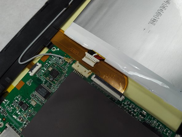
    • Using a small plastic opening tool; genteelly pull the connection off of the motherboard.

  4. Quantum View 10.1 Keyboard connector solid state board Replacement, Removing cover plate: 手順 4、 3の画像 1 Quantum View 10.1 Keyboard connector solid state board Replacement, Removing cover plate: 手順 4、 3の画像 2 Quantum View 10.1 Keyboard connector solid state board Replacement, Removing cover plate: 手順 4、 3の画像 3
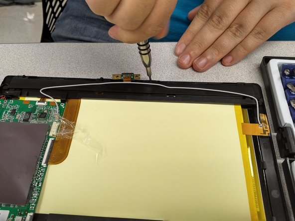
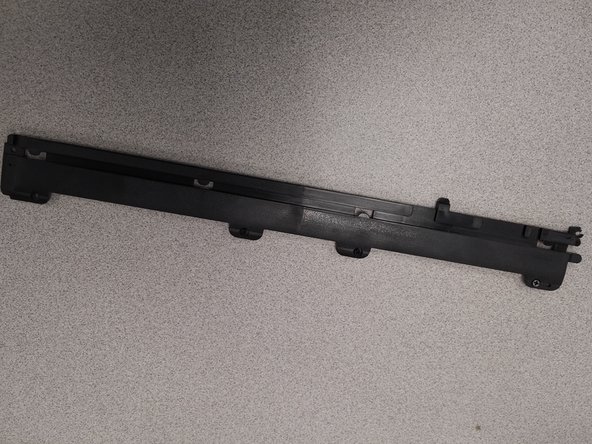
    • Using a PH00 Philips screwdriver bit remove 5 screws from the cover on top of the keyboard solid state board.

    • Then place cover off to the side.

  5. Quantum View 10.1 Keyboard connector solid state board Replacement, Removing the keyboard  solid state board: 手順 5、 3の画像 1 Quantum View 10.1 Keyboard connector solid state board Replacement, Removing the keyboard  solid state board: 手順 5、 3の画像 2 Quantum View 10.1 Keyboard connector solid state board Replacement, Removing the keyboard  solid state board: 手順 5、 3の画像 3
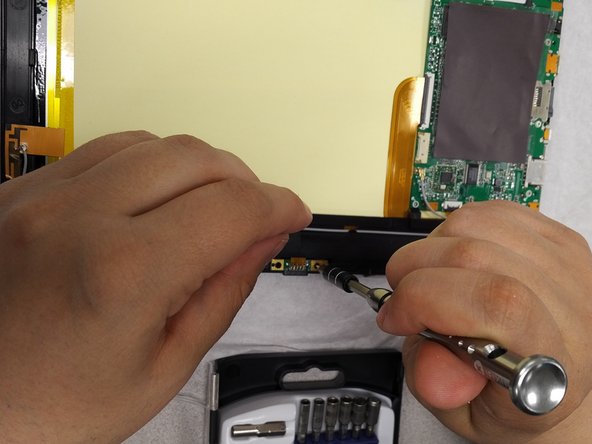
    • Using a PH000 Philips screw driver bit remove the two screws on securing the board to the case.

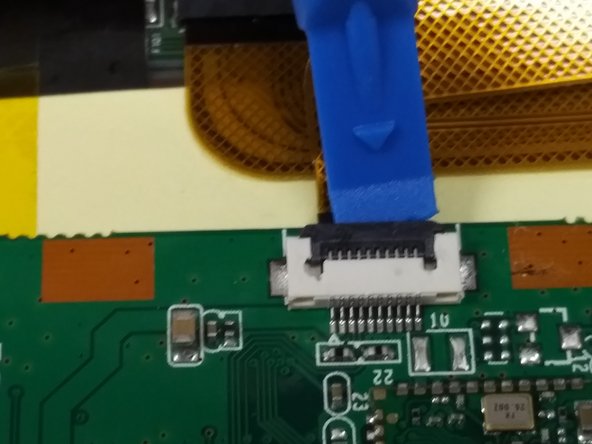
    • Then using a plastic opening tool slowly and carefully wedge the tool between the cable ribbon and the black connector portion. Then carefully rock the tool up and down to lift the connector hinge.

    • The board can now be removed.

終わりに

To reassemble your device, follow these instructions in reverse order.

作成者

3人の作成者と共同で作成されました。

stephen Munchinsky

メンバー登録日: 04/01/17

786 ポイント

7のガイドは作成済み

チーム

Gateway Community College Team 1 BPC270 36301 Gateway Community College Team 1 BPC270 36301人のメンバー

Community

4 メンバー

7のガイドは作成済み

0 件のコメント

コメントを追加

統計データ:

過去 24時間: 1

過去 7 日: 2

過去 30 日: 3

今までの合計 217