メインコンテンツにスキップ

Protocol Kaptur GPS Main Circuit Board Replacement

必要な工具と部品

  1. Protocol Kaptur GPS Main Circuit Board Replacement, Battery: 手順 1、 2の画像 1 Protocol Kaptur GPS Main Circuit Board Replacement, Battery: 手順 1、 2の画像 2
    • The battery is accessible through the back of the drone.

    • Press the tabs on both sides of the white stripe to pull the battery out.

  2. Protocol Kaptur GPS Main Circuit Board Replacement: 手順 2、 3の画像 1 Protocol Kaptur GPS Main Circuit Board Replacement: 手順 2、 3の画像 2 Protocol Kaptur GPS Main Circuit Board Replacement: 手順 2、 3の画像 3
    • Remove the screws starting with the three smaller ones on the top part of the battery.

    • Remove the three screws on the other side.

    • There are two screws tucked under where the yellow circle is located. You will need to remove the other screws first before you get to these two.

    • There should be one 7 mm Phillips head screw, three 6 mm Phillips head screws, and four 5 mm Phillips head screws.

  3. Protocol Kaptur GPS Main Circuit Board Replacement: 手順 3、 2の画像 1 Protocol Kaptur GPS Main Circuit Board Replacement: 手順 3、 2の画像 2
    • Remove the top piece, and gently pry the two halves apart. Divide the sticker if necessary.

  4. Protocol Kaptur GPS Main Circuit Board Replacement: 手順 4、 2の画像 1 Protocol Kaptur GPS Main Circuit Board Replacement: 手順 4、 2の画像 2
    • The battery is now removable from its container.

    • During reassembly, make sure the outlet is returned to its holder and faces the correct direction.

  5. Protocol Kaptur GPS Main Circuit Board Replacement, Main Circuit Board: 手順 5、 2の画像 1 Protocol Kaptur GPS Main Circuit Board Replacement, Main Circuit Board: 手順 5、 2の画像 2
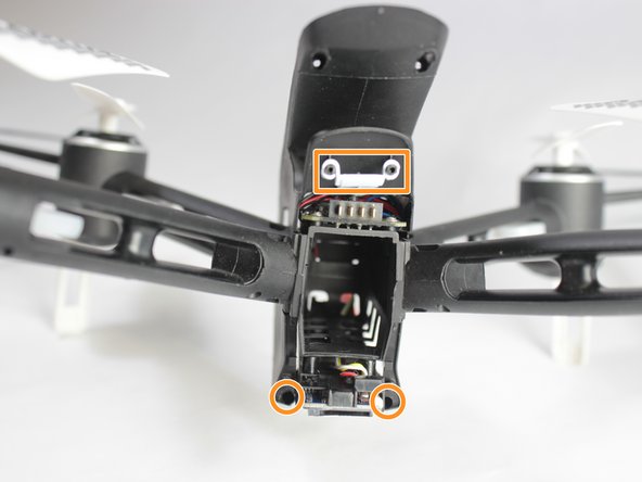
    • Remove the 4x 7mm screws on the top and bottom, and the 2x 5mm screws from the middle, then remove the back part of the housing.

    • Remove the two hidden screws at the bottom, and the white power button.

    • There will be 6x 7 mm Phillips head screws, and 2x 5 mm Phillips head screws.

  6. Protocol Kaptur GPS Main Circuit Board Replacement: 手順 6、 3の画像 1 Protocol Kaptur GPS Main Circuit Board Replacement: 手順 6、 3の画像 2 Protocol Kaptur GPS Main Circuit Board Replacement: 手順 6、 3の画像 3
    • Unplug all the cords from the circuit boards.

    • Carefully slide the main body right off the arms.

  7. Protocol Kaptur GPS Main Circuit Board Replacement: 手順 7、 2の画像 1 Protocol Kaptur GPS Main Circuit Board Replacement: 手順 7、 2の画像 2
    • Remove the four 4mm Phillips screws.

    • Desolder all cords on the circuit board, and pull the board up and out.

    • It is important to keep track of where the leads came from. Red/Blue and Black/White pairings belong to motors, whereas Black/Red pairings belong to lights. The ports are labeled on the board.

終わりに

To reassemble your device, follow these instructions in reverse order.

ある他の人がこのガイドを完成しました。

作成者

4人の作成者と共同で作成されました。

Connor Woitte

メンバー登録日: 02/15/18

858 ポイント

3のガイドは作成済み

チーム

UW Stout, Team S8-G6, Ogden Spring 2018 UW Stout, Team S8-G6, Ogden Spring 2018人のメンバー

UWSTOUT-OGDEN-S18S8G6

3 メンバー

4のガイドは作成済み

0 件のコメント

コメントを追加

統計データ:

過去 24時間: 0

過去 7 日: 6

過去 30 日: 6

今までの合計 770