メインコンテンツにスキップ

このバージョンは誤った内容を含んでいる可能性があります。最新の承認済みスナップショットに切り替えてください。

必要な工具と部品

  1. この手順は未翻訳です。 翻訳を手伝う。

    : 手順 1、 2の画像 1 : 手順 1、 2の画像 2
    • Use your thumbs to push the two battery retaining tabs away from the battery.

    • The battery should pop up enough to rotate it toward yourself and lift it out of the lower case.

  2. この手順は未翻訳です。 翻訳を手伝う。

    : 手順 2、 1の画像 1
    • Remove the three 2.3 mm Phillips screws securing the memory cover to the lower case.

  3. この手順は未翻訳です。 翻訳を手伝う。

    : 手順 3、 2の画像 1 : 手順 3、 2の画像 2
    • Lift the memory cover slightly and pull it toward yourself to remove it from the lower case.

  4. この手順は未翻訳です。 翻訳を手伝う。

    : 手順 4、 1の画像 1
    • Remove the following ten screws:

    • Two 14.7 mm shouldered Phillips.

    • Three 12.3 mm Phillips.

    • One 3.8 mm T8 Torx.

    • One 6.8 mm T8 Torx.

    • Three 1.3 mm Phillips.

  5. この手順は未翻訳です。 翻訳を手伝う。

    : 手順 5、 2の画像 1 : 手順 5、 2の画像 2
    • The ZIF cable is located underneath the bottom RAM slot. If your PowerBook has both RAM slots occupied, make sure to remove the RAM chip.

    • Use your fingernails to separate the ZIF cable lock away from its socket. (Move the two brown bits down 1mm)

    • The ZIF cable lock will move about a millimeter away from the socket before it stops (see picture 2). Do not try to remove the ZIF cable lock.

  6. この手順は未翻訳です。 翻訳を手伝う。

    : 手順 6、 1の画像 1
    • Use the tip of a spudger to slide the trackpad ribbon cable out of its socket.

  7. この手順は未翻訳です。 翻訳を手伝う。

    : 手順 7、 1の画像 1
    • Remove the four 3.4 mm Phillips screws from the PC card side of the PowerBook.

    • When replacing these screws, you must reinstall each screw in the correct order. Begin by installing the screw closest to the display hinge, and go out from there.

  8. この手順は未翻訳です。 翻訳を手伝う。

    : 手順 8、 1の画像 1
    • Remove the four 3.4 mm Phillips screws from the DVI connector side of the PowerBook.

    • When replacing these screws, you must reinstall each screw in the correct order. Begin by installing the screw closest to the display hinge, and go out from there.

    • During reassembly, make sure to reinstall the two screws on the right into their appropriate locations, and not the DVI port anchor holes.

  9. この手順は未翻訳です。 翻訳を手伝う。

    : 手順 9、 2の画像 1 : 手順 9、 2の画像 2
    • Depress the display latch release button and open your display.

  10. この手順は未翻訳です。 翻訳を手伝う。

    : 手順 10、 2の画像 1 : 手順 10、 2の画像 2
    • Starting near the display, lift the upper case straight up off the lower case, minding any cables that may get caught.

  11. この手順は未翻訳です。 翻訳を手伝う。

    : 手順 11、 1の画像 1
    • If necessary, peel back the strip of aluminum tape covering the modem cable.

  12. この手順は未翻訳です。 翻訳を手伝う。

    : 手順 12、 1の画像 1
    • Use the flat end of a spudger to pry the modem cable connector up off the modem.

  13. : 手順 13、 1の画像 1
    • モデムからRJ-11ケーブルの接続を外します。

  14. この手順は未翻訳です。 翻訳を手伝う。

    : 手順 14、 1の画像 1
    • Use a 4 mm nut driver to remove the two nuts securing the modem to the PC card cage.

  15. この手順は未翻訳です。 翻訳を手伝う。

    : 手順 15、 1の画像 1
    • Lift the modem straight up off the studs on the PC card cage.

  16. この手順は未翻訳です。 翻訳を手伝う。

    : 手順 16、 1の画像 1
    • Use the flat end of a spudger to pry the hard drive cable connector up off the logic board.

    • Bend the hard drive cable away from the PC card cage, giving yourself room to remove it.

  17. この手順は未翻訳です。 翻訳を手伝う。

    : 手順 17、 1の画像 1
    • Use the flat end of a spudger to pry the PC card cage connector up off the logic board.

  18. この手順は未翻訳です。 翻訳を手伝う。

    : 手順 18、 1の画像 1
    • Use the tip of a spudger to peel back the small strip of copper tape off the edge of the PC card cage near the side of the lower case.

  19. この手順は未翻訳です。 翻訳を手伝う。

    : 手順 19、 1の画像 1
    • Remove the four Phillips screws (2- 4 mm & 2 -6.8 mm ) securing the PC card cage to the lower case.

    • The two longer 6.8 mm shouldered screws belong in the end of the PC card cage closest to the logic board.

  20. この手順は未翻訳です。 翻訳を手伝う。

    : 手順 20、 2の画像 1 : 手順 20、 2の画像 2
    • Lift the PC card cage by its center piece and maneuver it out of the lower case.

  21. この手順は未翻訳です。 翻訳を手伝う。

    : 手順 21、 2の画像 1 : 手順 21、 2の画像 2
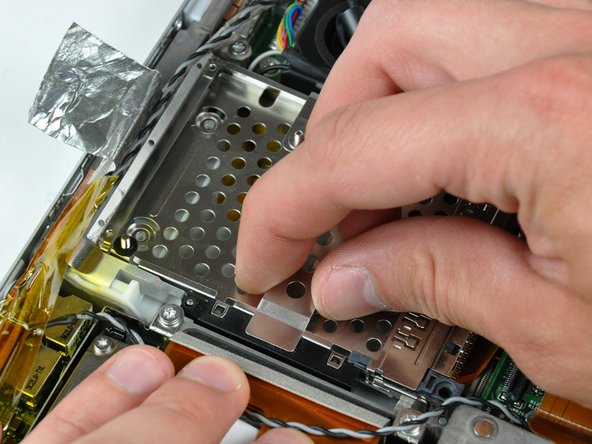
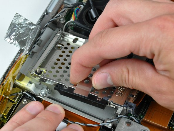
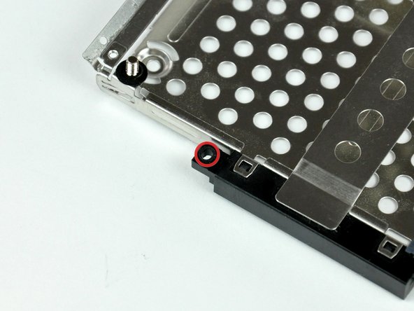
    • When reinstalling your PC card cage, be sure to insert the post sticking up from the PC card release button into the hole in the black plastic release mechanism on the PC card cage.

ゴール

作成者

4人の作成者と共同で作成されました。

Walter Galan

694,707 ポイント

1,203のガイドは作成済み

0 件のコメント

コメントを追加

統計データ:

過去 24時間: 3

過去 7 日: 4

過去 30 日: 5

今までの合計 2,588