Remove the four 3.4 mm Phillips screws from the PC card side of the PowerBook.
When replacing these screws, you must reinstall each screw in the correct order. Begin by installing the screw closest to the display hinge, and go out from there.
Remove the four 3.4 mm Phillips screws from the DVI connector side of the PowerBook.
When replacing these screws, you must reinstall each screw in the correct order. Begin by installing the screw closest to the display hinge, and go out from there.
During reassembly, make sure to reinstall the two screws on the right into their appropriate locations, and not the DVI port anchor holes.
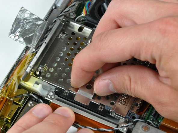
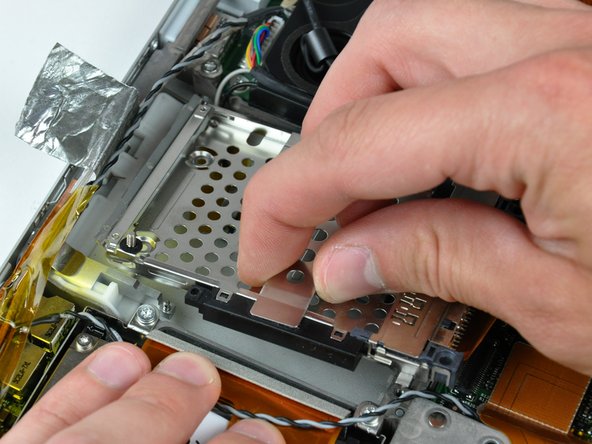
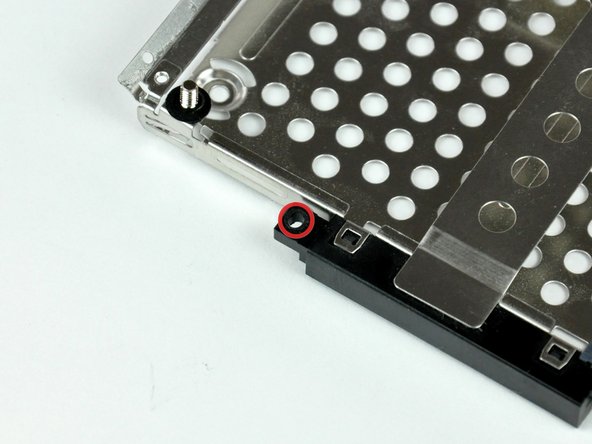
When reinstalling your PC card cage, be sure to insert the post sticking up from the PC card release button into the hole in the black plastic release mechanism on the PC card cage.
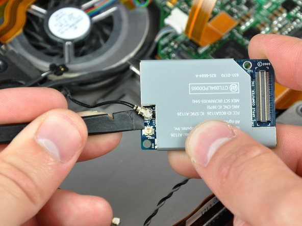
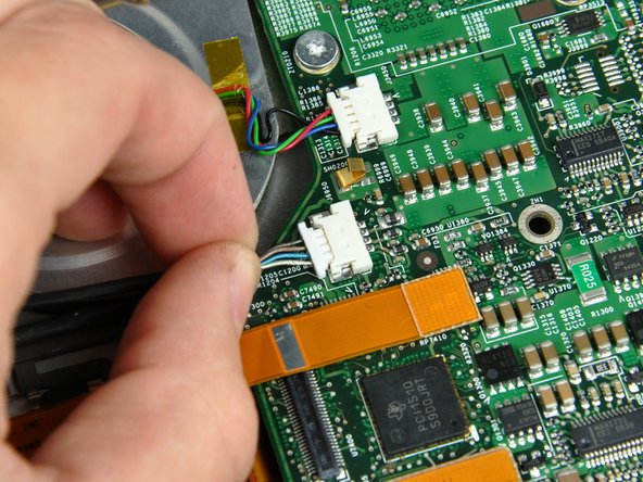
Remove the single 2.1 mm Phillips screw securing the AirPort/Bluetooth bracket to the lower case.
It is possible to remove the AirPort/Bluetooth board without removing this screw. Alternatively use the sharp end of a spudger to press the metal pressure connector (shown in orange) down through the hole in the AirPort/Bluetooth board, being careful to not break it off when prying the board up in the next step.
Here are a few tips for reassembling the display. These apply to both the left and right display brackets:
A small bracket (shown in red) near either side of the clutch cover is free to rotate about the display hinge and must be inserted behind the heat sink framework for the display to seat properly.
Before completely lowering the display onto the lower case, use a spudger to rotate the bracket toward the rear edge of your PowerBook, and insert the bracket between the heat sink framework and the adjacent spring. The second picture shows the bracket correctly installed.
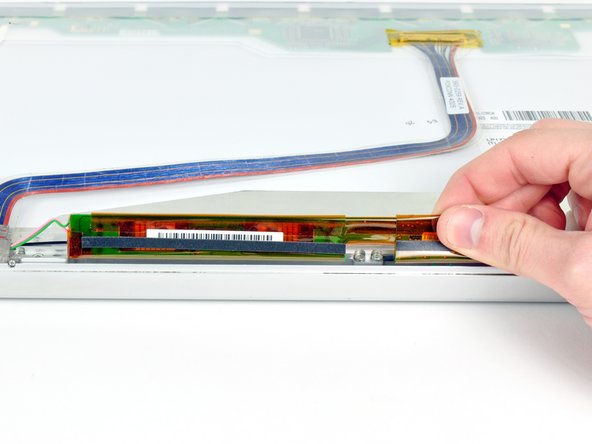
When removing the display screws, keep track of the thin metal bracket (shown in green) under the screws on the inner display bracket.
The outer display bracket (shown in orange) simply slides onto the spiral display spring. Be sure to press it on before installing your display into the lower case.
The picture at left (rear panel already removed) shows the locations of the metal clips (shown in red) that snap on to the front display bezel. In the next few steps, you will use a small flathead screwdriver to release these clips from a ridge around the perimeter of the front display bezel.
When prying in the following steps, be sure not to damage the antenna cables that run around the perimeter of the front display bezel.
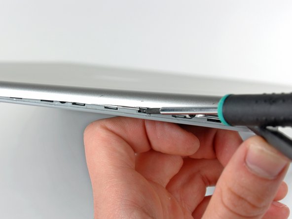
Insert the flat end of a spudger between the front display bezel and the plastic rim attached to the rear bezel near the lower right corner of the display.
Do not try to insert the spudger between the front display bezel and its plastic surround.
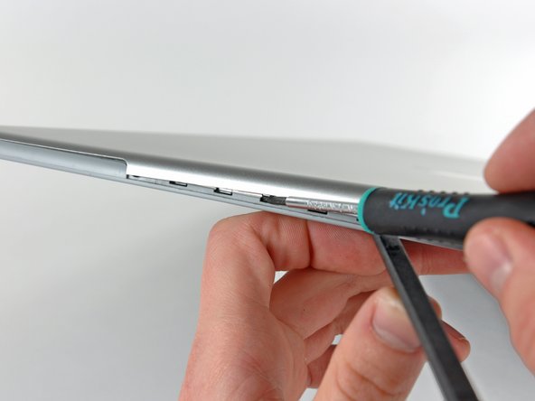
While carefully prying the rear display bezel away from the display assembly, use a small flathead screwdriver to pry the small steel clip nearest the bottom right corner of the display away from the edge of the front display bezel.
Repeat the above procedure until you've released all the clips along the right side of the display.
Insert the flat end of a spudger between the rear display bezel and the plastic surround of the front display bezel near the lower left corner of the display.
Carefully pry the rear display bezel away from the front display bezel to release a metal clip.
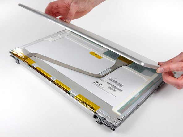
Slightly lift the lower edge of the rear display bezel and push it toward the top edge of the display, releasing the clips along the top edge of the rear display bezel.