メインコンテンツにスキップ

このバージョンは誤った内容を含んでいる可能性があります。最新の承認済みスナップショットに切り替えてください。

必要な工具と部品

  1. この手順は未翻訳です。 翻訳を手伝う。

    : 手順 1、 1の画像 1
    • Use a coin or a spudger to turn the battery locking screw 90 degrees clockwise.

    • Lift the battery out of the computer.

  2. この手順は未翻訳です。 翻訳を手伝う。

    , 上部ケース: 手順 2、 1の画像 1
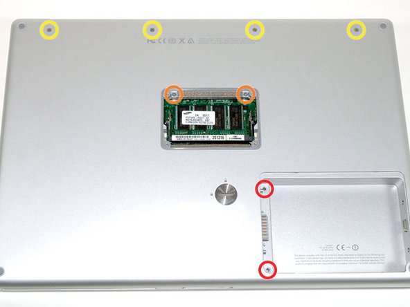
    • Remove the four Phillips screws from the memory door.

    • Slide the memory door away from the memory compartment.

    I recommend that you have several (ie 10-12) little cups nearby with a pen and some small scraps of paper to write on. As you remove screws, step by step, place that step's screws into one cup and label it "Step #X". That way, when you're putting everything back together, you won't have to guess as to which screws were for which step. I did this, on a recommendation of a friend who did this very same repair, and it made the reassembly even easier.

    beil - 返信

    Better still is to print out these instructions. Then as you remove screws, scotch tape them to the instruction sheet right on the place where it says to remove them. The tape keeps them from getting lost and the order can't be screwed up.

    Lavatop - 返信

    These were such great directions!! It was no harder than baking a cake. I didn't have a spudger, but a thin plastic chopstick worked fine. I took lavatop's tip to print out directions and tape the screws in order. It was great advice. Thanks IFixit!

    Karen Ann - 返信

    I found that a plastic ice cube tray works best in these situations.

    kostas16673 - 返信

  3. この手順は未翻訳です。 翻訳を手伝う。

    : 手順 3、 1の画像 1
    • Remove the following 8 screws:

    • Two 3 mm Phillips in the battery compartment, on either side of the battery contacts.

    • Two 12 mm Phillips on either side of the memory compartment.

    • Four 16 mm Phillips along the hinge.

  4. この手順は未翻訳です。 翻訳を手伝う。

    : 手順 4、 1の画像 1
    • Rotate the computer 90 degrees clockwise, so that the power receptacle faces you.

    • Remove the three 3 mm Phillips screws.

    • When replacing these screws, you must place each screw in the correct order. Begin by installing the screw closest to the display hinge, and go out from there.

  5. この手順は未翻訳です。 翻訳を手伝う。

    : 手順 5、 1の画像 1
    • Turn the computer 90 degrees clockwise so that the hinge faces you.

    • Remove the bottom 5 mm Phillips screw on either side of the hinge (two total).

    By "bottom", it means the top ones (if the computer were right-side-up), i.e. the ones closer to the lid.

    colleenthompson - 返信

  6. この手順は未翻訳です。 翻訳を手伝う。

    : 手順 6、 1の画像 1
    • Rotate the computer 90 degrees clockwise, so that the ports face you.

    • Remove the three 3 mm Phillips screws.

    • When replacing these screws, you must place each screw in the correct order. Begin by installing the screw closest to the display hinge, and go out from there.

    Don't be hasty! I've seen 2 laptops with a forlorn screw trapped in a video port screwhole, from where it's very difficult, if not impracticable, to remove it.

    colleenthompson - 返信

    colleenthompsonからの引用:

    Don't be hasty! I've seen 2 laptops with a forlorn screw trapped in a video port screwhole, from where it's very difficult, if not impracticable, to remove it.

    I've done that. Was not fun extracting the screw. I had to use a a large speaker magnet to get it out.

    Dan - 返信

  7. この手順は未翻訳です。 翻訳を手伝う。

    : 手順 7、 1の画像 1
    • Turn the computer over and open the display.

    • Remove the two 1.5 mm hex screws in either corner, next to the display (a T6 Torx driver will work, but repeated use will strip the screws).

  8. この手順は未翻訳です。 翻訳を手伝う。

    : 手順 8、 1の画像 1
    • Grasp the back corners of the upper case and pull up. Do not pull the upper case off yet; you still need to disconnect the keyboard and trackpad cable.

    • Lift the back of the case up and work your fingers along the sides, freeing the case as you go. Once you have freed the sides, you may need to rock the case up and down to free the front of the upper case.

  9. この手順は未翻訳です。 翻訳を手伝う。

    : 手順 9、 1の画像 1
    • Rotate the upper case up and toward the screen, so that the upper case rests against it.

    By "rotate" they mean tilt... You tilt the upper case (which contains the keyboard" up so that it rests against the screen. If you happen to have a helper nearby, get them to gently hold the upper case, when it's tilted up, in place so that you can do step 10.

    beil - 返信

    For this stage I found Step 9 and Step 10 in the guide for Hard Drive replacement were helpful in expanding on removal of top cover. See link here : PowerBook G4 Aluminum 15" 1-1.5 GHz Hard Drive Replacement

    Alastair Gill - 返信

  10. この手順は未翻訳です。 翻訳を手伝う。

    : 手順 10、 1の画像 1
    • Remove the orange tape securing the trackpad ribbon to the logic board.

    • Disconnect the trackpad ribbon from the logic board.

    • Remove the upper case from the computer.

  11. この手順は未翻訳です。 翻訳を手伝う。

    : 手順 11、 1の画像 1
    • Remove the 9.5 mm silver Phillips screw from the top of the right ambient light sensor board.

    • Remove the small 3 mm black Phillips screw from the bottom of the board.

  12. : 手順 12、 1の画像 1
    • コンピュータから右側環境光センサーボードを持ち上げます。

  13. この手順は未翻訳です。 翻訳を手伝う。

    : 手順 13、 1の画像 1
    • Remove the two black Phillips screws from the right speaker.

    • Lift the speaker away from the logic board and place it aside

  14. この手順は未翻訳です。 翻訳を手伝う。

    : 手順 14、 1の画像 1
    • Use your fingernail to flip up the black plastic flap locking the modem cable in place.

    • Slide the modem cable from its connector.

  15. この手順は未翻訳です。 翻訳を手伝う。

    : 手順 15、 1の画像 1
    • Disconnect the 13 indicated cables, removing tape as necessary.

    • When re-installing the board, make sure the two small connectors at the right hand side are above the board before inserting the screws.

    Is it possible for the various connectors to be labeled/identified? I'm trying to test a lower half but I don't know what exactly is missing, trying to figure it out by what's not plugged in.

    djfriar - 返信

  16. この手順は未翻訳です。 翻訳を手伝う。

    : 手順 16、 1の画像 1
    • Remove the following 8 Phillips screws from the logic board:

    • Three 6.5 mm in the upper left corner.

    • Five 4.5 mm around the edges.

  17. この手順は未翻訳です。 翻訳を手伝う。

    : 手順 17、 1の画像 1
    • Two cables still connect to the logic board and must be removed before pulling the board entirely out of the computer.

    • Use a spudger to gently (very gently) pry up the left side of the logic board.

    • If the logic board does not immediately come free, it may be necessary to soften the thermal paste between the logic board and heat sink. You can soften the thermal compound using a hairdryer. Move the hairdryer back and forth between the two fans about one inch above the logic board for one minute. At this point, the logic board should now come free easily.

  18. この手順は未翻訳です。 翻訳を手伝う。

    : 手順 18、 1の画像 1
    • Disconnect the DC-In connector from the left side of the logic board.

    It may be easier to disconnect the DC-in connector from the DC-Sound board end of the connector rather than from the logic board side of the connector

    Charles Fuller - 返信

  19. この手順は未翻訳です。 翻訳を手伝う。

    : 手順 19、 1の画像 1
    • Disconnect the battery cable from the front, left corner of the logic board.

  20. この手順は未翻訳です。 翻訳を手伝う。

    : 手順 20、 1の画像 1
    • Grasp the logic board at the left edge with one hand and at the thinnest section with the other hand. Lift the left edge of the board up to approximately a 30 degree angle (if you don't have your protractor handy, just lift until the DVI port clears the right hinge).

    • Once the logic board clears the ports, slide it out to the left.

    Great guide! Fantastic idea in the comments to print the instructions and then tape the screws by the step as you go. I found that it was easier to remove the screen and hinges before taking out the logic board. It made it much easier to remove and replace the right side of the logic board.

    wemerson - 返信

  21. この手順は未翻訳です。 翻訳を手伝う。

    : 手順 21、 1の画像 1
    • Important: when you reinstall a logic board, you'll need to replace the thermal paste that goes between the processor on the logic board and the heat sink. Failure to remove the old paste and apply a new layer can cause the computer to overheat and sustain damage.

    • To properly reassemble your PowerBook, you'll have to clean off and replace the old thermal compound. Use our Applying Thermal Paste Guide to prepare the processor and heat sink surfaces.

  22. この手順は未翻訳です。 翻訳を手伝う。

    : 手順 22、 1の画像 1
    • Use a firm plastic edge to scrape the thermal material off the processor.

    • When replacing the logic board, make sure all cables are routed around and above - not under - it, and to connect the two cables that do go beneath before pushing the board into place.

    • Place the logic board back in the computer, trying not to move it around once the processor has come into contact with the newly-applied thermal paste.

ゴール

13 の人々がこのガイドを完成させました。

作成者

7人の作成者と共同で作成されました。

iRobot

メンバー登録日: 09/24/09

1 ポイント

636のガイドは作成済み

2 件のコメント

I replaced my logic board using the wrong guide (Model A1138) but luckily there was only a few differences between guides

georgevp1 - 返信

Well, that's funny!

They are basically the same.

Ben Capehart -

コメントを追加

統計データ:

過去 24時間: 1

過去 7 日: 3

過去 30 日: 19

今までの合計 21,807