メインコンテンツにスキップ

この修理ガイドは変更されています。最新の未承認バージョンに切り替えます。

PowerBook G4 Aluminum 15" 1.5-1.67 GHz Battery Connector Replacement

必要な工具と部品

  1. PowerBook G4 Aluminum 15" 1.5-1.67 GHz Battery Connector Replacement, Battery: 手順 1、 1の画像 1
    • Use a coin or a spudger to turn the battery locking screw 90 degrees clockwise.

    • Lift the battery out of the computer.

  2. PowerBook G4 Aluminum 15" 1.5-1.67 GHz Battery Connector Replacement, Upper Case: 手順 2、 1の画像 1
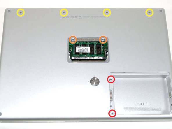
    • Remove the four Phillips screws from the memory door.

    • Slide the memory door away from the memory compartment.

  3. PowerBook G4 Aluminum 15" 1.5-1.67 GHz Battery Connector Replacement: 手順 3、 1の画像 1
    • Remove the following 8 screws:

    • Two 3 mm Phillips in the battery compartment, on either side of the battery contacts.

    • Two 12 mm Phillips on either side of the memory compartment.

    • Four 16 mm Phillips along the hinge.

  4. PowerBook G4 Aluminum 15" 1.5-1.67 GHz Battery Connector Replacement: 手順 4、 1の画像 1
    • Rotate the computer 90 degrees clockwise, so that the power receptacle faces you.

    • Remove the three 3 mm Phillips screws.

    • When replacing these screws, you must place each screw in the correct order. Begin by installing the screw closest to the display hinge, and go out from there.

  5. PowerBook G4 Aluminum 15" 1.5-1.67 GHz Battery Connector Replacement: 手順 5、 1の画像 1
    • Turn the computer 90 degrees clockwise so that the hinge faces you.

    • Remove the bottom 5 mm Phillips screw on either side of the hinge (two total).

  6. PowerBook G4 Aluminum 15" 1.5-1.67 GHz Battery Connector Replacement: 手順 6、 1の画像 1
    • Rotate the computer 90 degrees clockwise, so that the ports face you.

    • Remove the three 3 mm Phillips screws.

    • When replacing these screws, you must place each screw in the correct order. Begin by installing the screw closest to the display hinge, and go out from there.

  7. PowerBook G4 Aluminum 15" 1.5-1.67 GHz Battery Connector Replacement: 手順 7、 1の画像 1
    • Turn the computer over and open the display.

    • Remove the two 1.5 mm hex screws in either corner, next to the display (a T6 Torx driver will work, but repeated use will strip the screws).

  8. PowerBook G4 Aluminum 15" 1.5-1.67 GHz Battery Connector Replacement: 手順 8、 1の画像 1
    • Grasp the back corners of the upper case and pull up. Do not pull the upper case off yet; you still need to disconnect the keyboard and trackpad cable.

    • Lift the back of the case up and work your fingers along the sides, freeing the case as you go. Once you have freed the sides, you may need to rock the case up and down to free the front of the upper case.

  9. PowerBook G4 Aluminum 15" 1.5-1.67 GHz Battery Connector Replacement: 手順 9、 1の画像 1
    • Rotate the upper case up and toward the screen, so that the upper case rests against it.

  10. PowerBook G4 Aluminum 15" 1.5-1.67 GHz Battery Connector Replacement: 手順 10、 1の画像 1
    • Remove the orange tape securing the trackpad ribbon to the logic board.

    • Disconnect the trackpad ribbon from the logic board.

    • Remove the upper case from the computer.

  11. PowerBook G4 Aluminum 15" 1.5-1.67 GHz Battery Connector Replacement, Battery Connector: 手順 11、 1の画像 1
    • Disconnect the sleep light cable from the logic board to gain access to the battery connector cable beneath it.

  12. PowerBook G4 Aluminum 15" 1.5-1.67 GHz Battery Connector Replacement: 手順 12、 1の画像 1
    • Disconnect the battery connector cable from beneath the logic board.

    • While it's easier to pull the thick battery connector cable out with your fingers, a spudger will help you push it back into place when putting the computer back together.

  13. PowerBook G4 Aluminum 15" 1.5-1.67 GHz Battery Connector Replacement: 手順 13、 1の画像 1
    • Remove the two silver Phillips screws from the battery connector.

    • Remove a third Phillips screw near the bottom left corner of the hard drive that pins down a ground loop.

    • The screws with the larger heads go on the battery connector.

  14. PowerBook G4 Aluminum 15" 1.5-1.67 GHz Battery Connector Replacement: 手順 14、 1の画像 1
    • Lift the battery connector out of the computer, removing tape as necessary.

終わりに

To reassemble your device, follow these instructions in reverse order.

作成者

2人の作成者と共同で作成されました。

iRobot

メンバー登録日: 09/24/09

1 ポイント

636のガイドは作成済み

0 件のコメント

コメントを追加

統計データ:

過去 24時間: 1

過去 7 日: 4

過去 30 日: 8

今までの合計 7,307