メインコンテンツにスキップ

Power Mac G4 Quicksilver Logic Board Replacement

必要な工具と部品

  1. Power Mac G4 Quicksilver Logic Board Replacement, Opening the case: 手順 1、 1の画像 1
    • The handle to open your computer is located on top of the right side panel.

  2. Power Mac G4 Quicksilver Logic Board Replacement: 手順 2、 2の画像 1 Power Mac G4 Quicksilver Logic Board Replacement: 手順 2、 2の画像 2
    • Grab the circular handle and pull outward.

  3. Power Mac G4 Quicksilver Logic Board Replacement: 手順 3、 1の画像 1
    • Your computer is now open and ready for repair.

  4. Power Mac G4 Quicksilver Logic Board Replacement, Video Adapter: 手順 4、 1の画像 1
    • This is your Power Mac G4's video adapter.

  5. Power Mac G4 Quicksilver Logic Board Replacement: 手順 5、 1の画像 1
    • Start by removing the screw holding the card to the chassis as shown.

  6. Power Mac G4 Quicksilver Logic Board Replacement: 手順 6、 1の画像 1
    • Before lifting the card out, this small plastic tab needs to be pulled back there by releasing it entirely.

  7. Power Mac G4 Quicksilver Logic Board Replacement: 手順 7、 2の画像 1 Power Mac G4 Quicksilver Logic Board Replacement: 手順 7、 2の画像 2
    • With the tab and screw removed, lift the card straight out.

    • When putting the card back in, take care to apply even pressure across the top with your thumbs. This will avoid damaging the card.

  8. Power Mac G4 Quicksilver Logic Board Replacement, Logic Board: 手順 8、 1の画像 1
    • Disconnect both the power cables and IDE cable from the mother board.

  9. Power Mac G4 Quicksilver Logic Board Replacement: 手順 9、 1の画像 1
    • Remove these three screws that hold the motherboard fan and modem connector to the chassis.

  10. Power Mac G4 Quicksilver Logic Board Replacement: 手順 10、 1の画像 1
    • Remove the four screws shown to free the mother board from the chassis.

  11. Power Mac G4 Quicksilver Logic Board Replacement: 手順 11、 3の画像 1 Power Mac G4 Quicksilver Logic Board Replacement: 手順 11、 3の画像 2 Power Mac G4 Quicksilver Logic Board Replacement: 手順 11、 3の画像 3
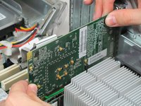
    • Lift the fan shroud and fan straight up and out. Take care to disconnect the indicated connector

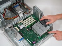
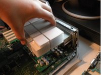
    • Remove the heatsink clamps with a flathead screwdriver and do the same for the other side.

    • Lift off the heatsink and remove the 4 screws of the CPU board.

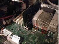
    • There are 4 pins: remove the 3 pins near the RAM but not the pin nearest You.

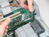
    • You are now ready to slide gently (and without ANY difficult) the motherboard. Lift up and the game is done.

終わりに

To reassemble your device, follow these instructions in reverse order.

10 の人々がこのガイドを完成させました。

作成者

4人の作成者と共同で作成されました。

Cameron Christensen

メンバー登録日: 01/20/10

590 ポイント

3のガイドは作成済み

チーム

Cal Poly, Team 14-41, Regan Winter 2010 Cal Poly, Team 14-41, Regan Winter 2010人のメンバー

CPSU-REGAN-W10S14G41

4 メンバー

17のガイドは作成済み

0 件のコメント

コメントを追加

統計データ:

過去 24時間: 0

過去 7 日: 12

過去 30 日: 30

今までの合計 16,842