このバージョンは誤った内容を含んでいる可能性があります。最新の承認済みスナップショットに切り替えてください。
必要な工具と部品
-
この手順は未翻訳です。 翻訳を手伝う。
-
Turn the entire device over, so that the underside of the device is facing upward.
-
With the underside of the device facing up, locate the 11mm screw found in each far corner of the device. Remove the single 11mm screw from each of the four corners, using the Phillips #0 screwdriver.
-
-
この手順は未翻訳です。 翻訳を手伝う。
-
Turn the device so that the underside faces you, and the edge where the case and device bind, faces upward. The opening of the device should be face down.
-
In this position you will see a crease line between the device and the top cover. Gently Insert your blue plastic opening tool into the crack of the crease line, between the front and back cover to separate them.
-
Separate the halves of the case.
-
-
この手順は未翻訳です。 翻訳を手伝う。
-
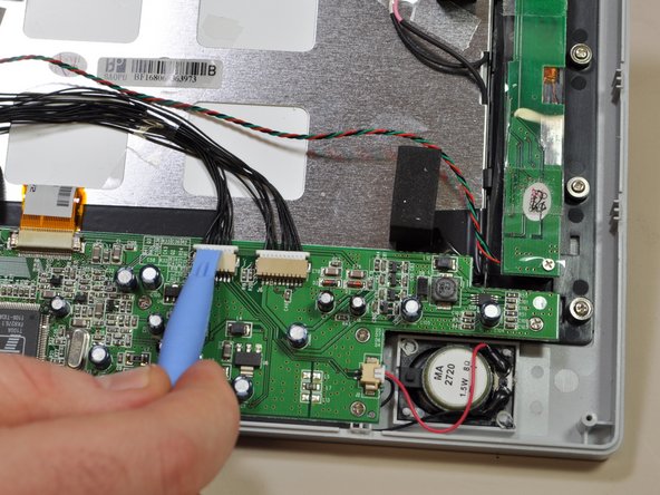
Locate the input/output board on the top left hand corner of the device. It will look like a green circuit board with wires protruding and connecting to the case cover.
-
Using your blue plastic opening tool, disconnect the multicolored wires located on the input/output board. These will be the same multicolored wires that connect the back cover to the input/output board.
-
-
この手順は未翻訳です。 翻訳を手伝う。
-
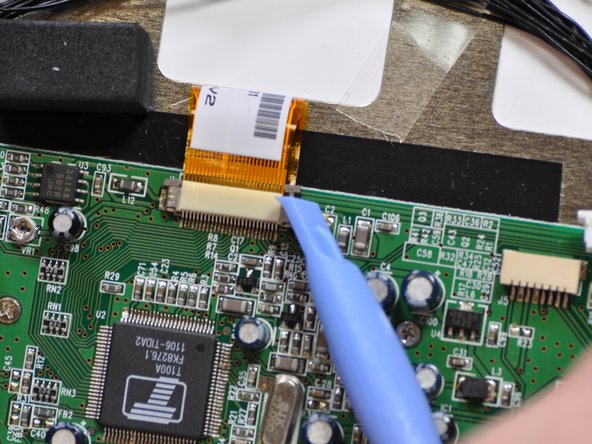
Remove the five different connections to this board. Two from the speakers, two from input/output board and the orange ribbon cable.
-
Remove connections from input/output board and speaker with the plastic opening tool.
-
Remove the orange ribbon cable using the plastic opening tool to release the two brown retention tabs.
-


チーム

Cal Poly, Team 8-14, Maness Winter 2012 Cal Poly, Team 8-14, Maness Winter 2012人のメンバー
CPSU-MANESS-W12S8G14
4 メンバー
8のガイドは作成済み