メインコンテンツにスキップ

このバージョンは誤った内容を含んでいる可能性があります。最新の承認済みスナップショットに切り替えてください。

必要な工具と部品

  1. この手順は未翻訳です。 翻訳を手伝う。

    : 手順 1、 1の画像 1
    • Remove the battery and memory card from the device.

  2. この手順は未翻訳です。 翻訳を手伝う。

    : 手順 2、 1の画像 1
    • Remove 4 screws from the right side of the camera.

    • There are two 3.4mm screws at the top.

    • There are two 2.2mm screws at the bottom.

  3. この手順は未翻訳です。 翻訳を手伝う。

    : 手順 3、 1の画像 1
    • Remove the single 3.4mm screw on the left side of the camera.

  4. この手順は未翻訳です。 翻訳を手伝う。

    : 手順 4、 1の画像 1
    • Remove 5 screws from the base of the camera.

    • There are two 2.2mm screws next to the battery compartment.

    • There are three 4mm screws around the tripod mount.

  5. この手順は未翻訳です。 翻訳を手伝う。

    : 手順 5、 1の画像 1
    • Slowly slide the back cover away from the device

    • The back casing is held in place by two ribbon cables. Do not pull the back cover too far from the camera.

  6. この手順は未翻訳です。 翻訳を手伝う。

    : 手順 6、 2の画像 1 : 手順 6、 2の画像 2
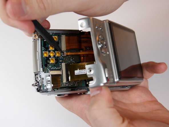
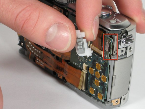
    • Detach both ribbon cables using a spudger.

    • Use the tip of the spudger to lift the black clip upward, unlocking the ribbon cable.

  7. この手順は未翻訳です。 翻訳を手伝う。

    : 手順 7、 1の画像 1
    • Remove the back casing from the camera.

  8. この手順は未翻訳です。 翻訳を手伝う。

    : 手順 8、 2の画像 1 : 手順 8、 2の画像 2
    • Use the spudger to remove the ribbon cable connecting the lens casing to the circuit board by lifting up the black clip.

    • Carefully remove the function switch cover. This unit snaps on and off.

  9. この手順は未翻訳です。 翻訳を手伝う。

    : 手順 9、 1の画像 1
    • Carefully unsnap the front logic board from the rear logic board using a spudger.

  10. この手順は未翻訳です。 翻訳を手伝う。

    : 手順 10、 2の画像 1 : 手順 10、 2の画像 2
    • Slide the entire top part of the camera that is attached to the logic board, horizontally away from the camera.

  11. この手順は未翻訳です。 翻訳を手伝う。

    : 手順 11、 3の画像 1 : 手順 11、 3の画像 2 : 手順 11、 3の画像 3
    • Remove the ribbon cable from the top connection panel by unlocking the black clip with a spudger.

    • This leaves you with the logic board and the top connection panel separate and free from the camera

  12. この手順は未翻訳です。 翻訳を手伝う。

    : 手順 12、 1の画像 1
    • Use a spudger to detach the ribbon cable from the circuit board. Lift the black clip up to unlock it as before.

  13. この手順は未翻訳です。 翻訳を手伝う。

    : 手順 13、 1の画像 1
    • Remove the 3 screws holding the lens assembly in place.

    • The two screws on the left are 4.5mm with washers.

    • The single screw on the right is 4mm.

  14. この手順は未翻訳です。 翻訳を手伝う。

    : 手順 14、 1の画像 1
    • Push the lens assembly slightly toward the circuit board, and pull the left side out of the casing first. You will have to wiggle this out gently.

  15. この手順は未翻訳です。 翻訳を手伝う。

    : 手順 15、 2の画像 1 : 手順 15、 2の画像 2
    • Remove the entire assembly out of the casing.

    • The ribbons on the left and bottom of the assembly simply rest on the camera housing.

  16. この手順は未翻訳です。 翻訳を手伝う。

    : 手順 16、 1の画像 1
    • Use the spudger to unclip the top ribbon cable from the circuit board.

  17. この手順は未翻訳です。 翻訳を手伝う。

    : 手順 17、 1の画像 1
    • Remove the single 2mm screw in the bottom right corner of the circuit board

  18. この手順は未翻訳です。 翻訳を手伝う。

    : 手順 18、 2の画像 1 : 手順 18、 2の画像 2
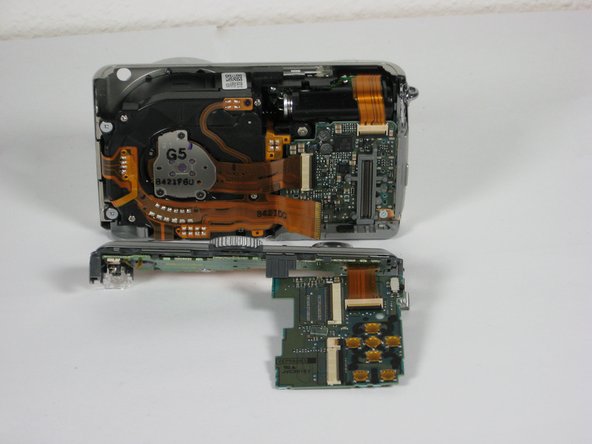
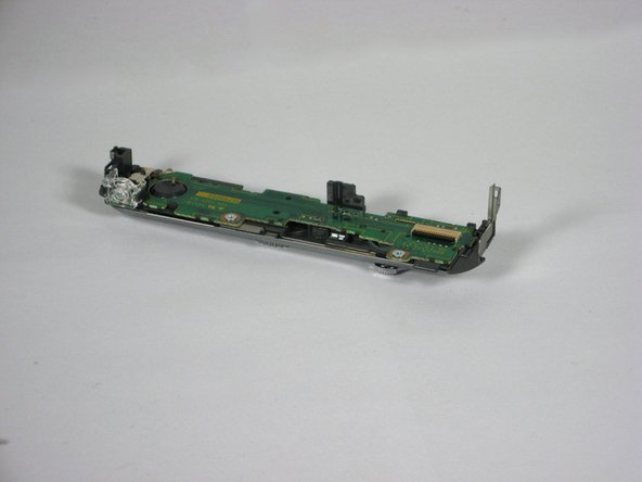
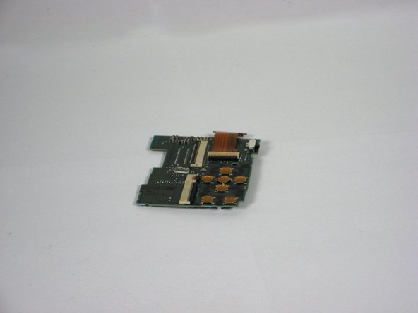
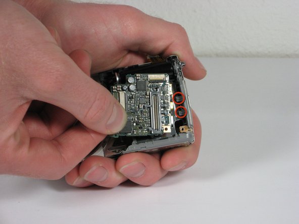
    • Gently slide the circuit board out away from the port connections. Pull it toward where the lens used to be. Some wiggling may be necessary to remove.

    • The circuit board is fitted into slots attached to the side of the camera. Do not angle upwards to remove.

  19. この手順は未翻訳です。 翻訳を手伝う。

    : 手順 19、 1の画像 1
    • Take note of how the slots fit into the circuit board for easy replacement.

  20. この手順は未翻訳です。 翻訳を手伝う。

    : 手順 20、 1の画像 1
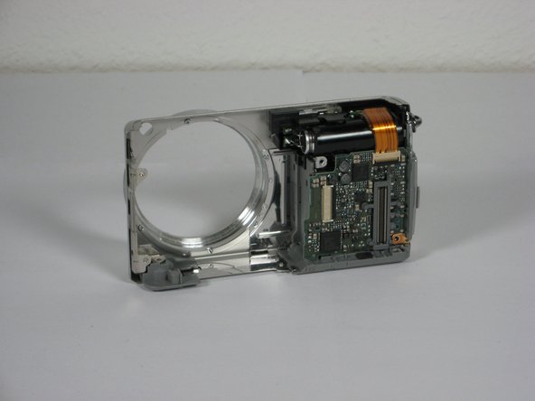
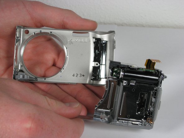
    • After removing the AV circuit board you are left with the front casing attached to the inner casing and flash unit.

    • First you must remove two 3.5mm blue screws near the hole of the lens that attach the inner casing.

  21. この手順は未翻訳です。 翻訳を手伝う。

    : 手順 21、 1の画像 1
    • Remove the 3.5mm colorless screw that lays within the square opening of the inner casing.

  22. この手順は未翻訳です。 翻訳を手伝う。

    : 手順 22、 1の画像 1
    • Remove the front casing from the rest of the device.

  23. この手順は未翻訳です。 翻訳を手伝う。

    : 手順 23、 2の画像 1 : 手順 23、 2の画像 2
    • Use a spudger to carefully lift the small clip located to the left of the unit.

    • Lift the flash unit out of the case.

ゴール

2 の人々がこのガイドを完成させました。

作成者

5人の作成者と共同で作成されました。

Guadalupe

メンバー登録日: 10/11/10

90 ポイント

1ガイドが承認済み

チーム

Cal Poly, Team 9-21, Regan Fall 2010 Cal Poly, Team 9-21, Regan Fall 2010人のメンバー

CPSU-REGAN-F10S9G21

4 メンバー

14のガイドは作成済み

2 件のコメント

Very easy to follow instructions. Thank you very much!!!

Mike Hair - 返信

Thank you for showing me how to fix my LUMIX TZ5 Camera.. I will do this as soon as I get the replacement flash.

Carlos

marooned7777 - 返信

コメントを追加

統計データ:

過去 24時間: 4

過去 7 日: 13

過去 30 日: 24

今までの合計 14,040