メインコンテンツにスキップ

このバージョンは誤った内容を含んでいる可能性があります。最新の承認済みスナップショットに切り替えてください。

必要な工具と部品

  1. この手順は未翻訳です。 翻訳を手伝う。

    : 手順 1、 2の画像 1 : 手順 1、 2の画像 2
    • Remove both of the 3 mm screws on the bottom of the camera connected to the side panel.

  2. この手順は未翻訳です。 翻訳を手伝う。

    : 手順 2、 2の画像 1 : 手順 2、 2の画像 2
    • Remove the remaining 3 mm screw holding on the side panel and remove the panel entirely.

  3. この手順は未翻訳です。 翻訳を手伝う。

    : 手順 3、 2の画像 1 : 手順 3、 2の画像 2
    • On the opposite side of the camera, remove the two 3 mm screws.

    • Remove the bottom side panel and place it with its respective 3 mm screw.

  4. この手順は未翻訳です。 翻訳を手伝う。

    : 手順 4、 3の画像 1 : 手順 4、 3の画像 2 : 手順 4、 3の画像 3
    • Remove the front panel (the panel around the lens casing) from the camera.

    • Remove the two ribbon cables connected to the back panel (the panel this the LCD screen) by lifting up on their respective tabs and gently pulling out the cord.

    • Caution: When removing the back panel, the two ribbon cables are relatively delicate and must both be disconnected before the panel can be entirely removed.

    • Remove the back panel from the camera.

  5. この手順は未翻訳です。 翻訳を手伝う。

    : 手順 5、 1の画像 1
    • Remove the top control panel (connected to the flash battery) from the camera.

    • The top control panel is connected to the rest of the camera by a delicate multi-pin plug. Be careful as to not bend the pins!

  6. この手順は未翻訳です。 翻訳を手伝う。

    : 手順 6、 2の画像 1 : 手順 6、 2の画像 2
    • Locate and remove the silver 2mm screw on the protection panel.

    • Remove the three black 8mm screws that remain.

    • Be sure to remember which length of screw goes to which slot. Failing to do so could damage your device.

    • Proceed to remove the protection panel entirely.

  7. この手順は未翻訳です。 翻訳を手伝う。

    : 手順 7、 1の画像 1
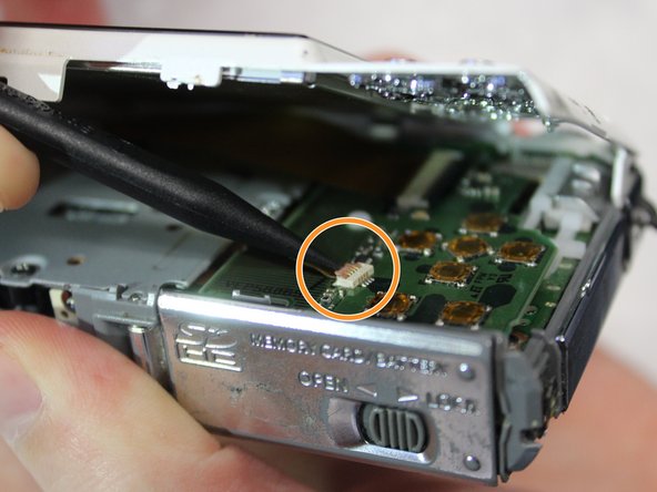
    • Insert the flat end of a plastic spudger underneath the motherboard and twist. This will disconnect the board from the device and allow it to be removed.

  8. この手順は未翻訳です。 翻訳を手伝う。

    : 手順 8、 1の画像 1
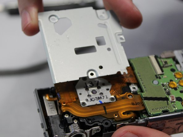
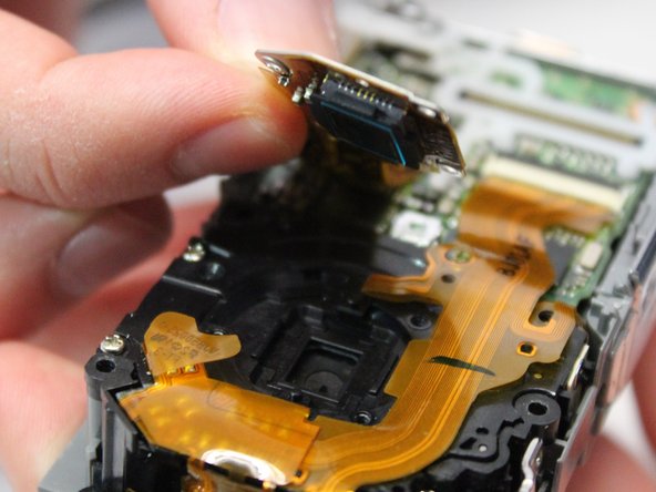
    • Use the pointed end of the spudger to lift the black tabs holding the ribbon cable connected to the photoreceptor in place.

    • Before pulling the cable free, be sure to complete the next step (removing the screws) as the ribbon cables are delicate and must be handled with care.

  9. この手順は未翻訳です。 翻訳を手伝う。

    : 手順 9、 2の画像 1 : 手順 9、 2の画像 2
    • Remove the three 3mm screws holding the photoreceptor in place.

    • Carefully lift the photoreceptor, disconnecting the ribbon cable and remove the photoreceptor from the device.

ゴール

ある他の人がこのガイドを完成しました。

作成者

3人の作成者と共同で作成されました。

Zhentao

メンバー登録日: 01/30/18

247 ポイント

2のガイドは作成済み

チーム

Baylor, Team S2-G3, Johnson Spring 2018 Baylor, Team S2-G3, Johnson Spring 2018人のメンバー

BU-JOHNSON-S18S2G3

3 メンバー

6のガイドは作成済み

0 件のコメント

コメントを追加

統計データ:

過去 24時間: 1

過去 7 日: 4

過去 30 日: 16

今までの合計 281