はじめに
The process of removing covers and simple internal components requires minimal technical experience.
必要な工具と部品
-
-
Unplug the device from any energy sources.
-
Lift the top cover of the scanner.
-
Use a plastic opening tool to remove the plastic frame surrounding the glass.
 FixBotに聞いてみる
-
-
-
Use a T10 screwdriver to unscrew the two screws that fasten the frame to the printer hood.
-
-
-
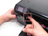
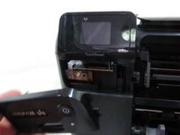
Put your finger behind the panel with the power button.
-
Then, pull the piece outwards.
-
-
-
-
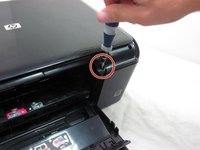
Unscrew the screw inside the power button panel space.
-
Then, unscrew the screw that is across the printer slider.
-
-
-
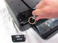
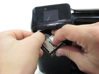
Pull the white circuit board outwards which is located under the small screen.
-
Unplug the small ribbon cable from the circuit board.
-
-
-
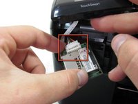
Unplug the small ribbon cable from the circuit board. Be careful when you unplug the ribbon cable not to use too much force. Using too much force may damage or rip the cable.
-
-
-
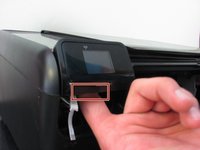
Pull the memory card reader's circuit board out.
-
Detach the white wiring connector from the back of the circuit board.
-
-
-
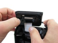
Put your finger behind the small screen.
-
Then, pull it up.
-
Disconnect the ribbon cable from the small screen.
-


To reassemble, simply follow the steps in reverse order.
9 の人々がこのガイドを完成させました。
チーム

Cal Poly, Team 2-11, Propen Fall 2012 Cal Poly, Team 2-11, Propen Fall 2012人のメンバー
CPSU-PROPEN-F12S2G11
4 メンバー
6のガイドは作成済み
3件のガイドコメント
Excellent helpful easy to follow instructions. Thanks.
In step 7, removal of the Touch Pad, I was not able to locate the release clip. Feeling around, what I thought was the latch was a ribbon cable that I distorted but didn't destroy. The top came off without the Touch Pad removal. Once the top was off, I located a latch on the back right of the Touch Pad, but once released, it didn't help to free up the Touch Pad. I couldn't get the Touch Pad off.