メインコンテンツにスキップ

Optical Laser Lens Power Adjustment

必要な工具と部品

  1. Optical Laser Lens Power Adjustment, Top Case: 手順 1、 3の画像 1 Optical Laser Lens Power Adjustment, Top Case: 手順 1、 3の画像 2 Optical Laser Lens Power Adjustment, Top Case: 手順 1、 3の画像 3
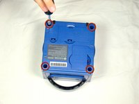
    • Turn over the Gamecube so that the bottom side is facing up.

    • Use the 4.5 mm Gamebit screwdriver to remove all four screws.

  2. Optical Laser Lens Power Adjustment: 手順 2、 3の画像 1 Optical Laser Lens Power Adjustment: 手順 2、 3の画像 2 Optical Laser Lens Power Adjustment: 手順 2、 3の画像 3
    • With the bottom side of the GameCube facing upward and the screws removed, carefully pull the outer shell of the unit away from the top half.

    • Move the GameCube so that the inside is facing upwards.

  3. Optical Laser Lens Power Adjustment, Removing the back panel: 手順 3、 1の画像 1
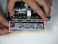
    • Gently press down on the clips located on either side of the back panel.

    • Carefully remove the back panel from the GameCube.

  4. Optical Laser Lens Power Adjustment: 手順 4、 1の画像 1
    • Unclip the controller ports at the front of the unit.

    • A ribbon cable (outlined in orange) is still attached to the unit. Do not disconnect this cable.

    • Controller ports are where the controllers plug into the game console, and are a half circular shape.

  5. Optical Laser Lens Power Adjustment, Separate the casing: 手順 5、 2の画像 1 Optical Laser Lens Power Adjustment, Separate the casing: 手順 5、 2の画像 2
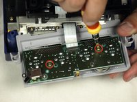
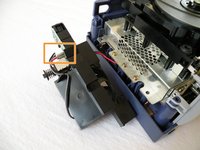
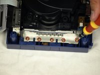
    • Use a Phillips #2 screwdriver to remove the two screws on the back of the control port.

    • Carefully separate the gray outer casing of the control port and the circuit board.

  6. Optical Laser Lens Power Adjustment, Remove Nintendo GameCube Optical Drive Assembly: 手順 6、 2の画像 1 Optical Laser Lens Power Adjustment, Remove Nintendo GameCube Optical Drive Assembly: 手順 6、 2の画像 2
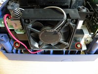
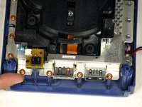
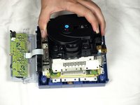
    • The left side of the unit contains the cooling fan and its housing.

    • Carefully remove the two screws attaching the cooling fan housing to the unit.

    • Do not detach the red and black cooling fan wire from the main unit. Boxed in orange.

  7. Optical Laser Lens Power Adjustment: 手順 7、 2の画像 1 Optical Laser Lens Power Adjustment: 手順 7、 2の画像 2
    • Remove the four Phillips #1 screws retaining the ground springs.

    • Carefully remove the ground springs from the main unit.

  8. Optical Laser Lens Power Adjustment: 手順 8、 2の画像 1 Optical Laser Lens Power Adjustment: 手順 8、 2の画像 2
    • The optical drive is secured to a metal plate.

    • Using a Phillips #2 screwdriver, unscrew the twelve screws that are around the outer edge of the optical drive.

  9. Optical Laser Lens Power Adjustment, Remove the assembly: 手順 9、 3の画像 1 Optical Laser Lens Power Adjustment, Remove the assembly: 手順 9、 3の画像 2 Optical Laser Lens Power Adjustment, Remove the assembly: 手順 9、 3の画像 3
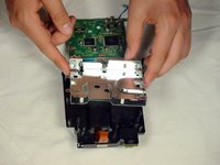
    • Carefully separate the optical drive assembly from the rest of the GameCube unit.

    • The optical drive assembly is secured to the motherboard underneath by a slot; some force may be required to carefully free the assembly.

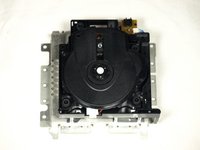
    • The metal plate and the actual optical drive will remain attached.

  10. Optical Laser Lens Power Adjustment, Optical Drive Assembly: 手順 10、 3の画像 1 Optical Laser Lens Power Adjustment, Optical Drive Assembly: 手順 10、 3の画像 2 Optical Laser Lens Power Adjustment, Optical Drive Assembly: 手順 10、 3の画像 3
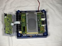
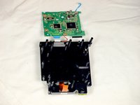
    • At this point, your optical drive assembly should be separated from your GameCube.

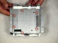
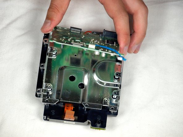
    • Flip the optical drive assembly upside down.

    • Remove the six screws with a Phillips #1 screwdriver.

    • Gently lift and remove the metal plate.

    • Be careful not to disturb the brown ribbon cable.

  11. Optical Laser Lens Power Adjustment: 手順 11、 3の画像 1 Optical Laser Lens Power Adjustment: 手順 11、 3の画像 2 Optical Laser Lens Power Adjustment: 手順 11、 3の画像 3
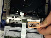
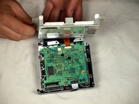
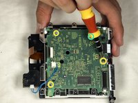
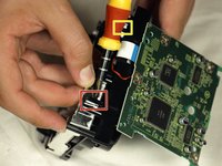
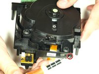
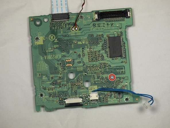
    • Remove the blue wire by gently pulling.

    • Don't pull on either the wire itself or the connector attached to the board.

    • Disconnect the brown cable. This is done by gently pulling the black tab away from the white plastic. This will loosen the tension on the brown cable, allowing it to slide away from the tab gently.

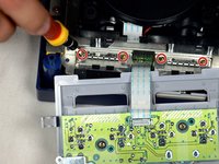
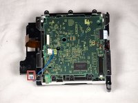
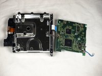
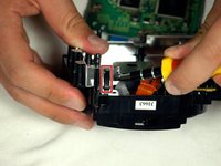
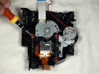
    • Remove the four Phillips #1 screws connecting the circuit board to the optical drive assembly.

    • The fourth screw is located behind the screwdriver in the third picture.

  12. Optical Laser Lens Power Adjustment: 手順 12、 3の画像 1 Optical Laser Lens Power Adjustment: 手順 12、 3の画像 2 Optical Laser Lens Power Adjustment: 手順 12、 3の画像 3
    • Release the small clip holding the board down.

    • Gently remove the circuit board (the large green square) as shown in the three pictures.

    • DO NOT SEPARATE the red wire or the white ribbon cable connecting the circuit board to the metal plate.

    • Red Wire

    • White ribbon Cable

  13. Optical Laser Lens Power Adjustment: 手順 13、 3の画像 1 Optical Laser Lens Power Adjustment: 手順 13、 3の画像 2 Optical Laser Lens Power Adjustment: 手順 13、 3の画像 3
    • Use a flathead screwdriver to carefully release the four plastic clips holding the drive assembly together.

    • Carefully use a screwdriver as leverage to unscrew and release the last clip.

  14. Optical Laser Lens Power Adjustment: 手順 14、 3の画像 1 Optical Laser Lens Power Adjustment: 手順 14、 3の画像 2 Optical Laser Lens Power Adjustment: 手順 14、 3の画像 3
    • Gently lift the metal plate off the drive assembly.

    • Be careful not to sever the red wire or the white ribbon cable still attached to the two halves of the drive assembly.

    • Then, flip the two halves of the drive assembly upside down.

  15. Optical Laser Lens Power Adjustment: 手順 15、 3の画像 1 Optical Laser Lens Power Adjustment: 手順 15、 3の画像 2 Optical Laser Lens Power Adjustment: 手順 15、 3の画像 3
    • Use a flathead screwdriver to release the two clips located on the back half of the drive assembly.

    • The final clip doesn't need to be released; the top half of the drive assembly will slide away from the lower half.

    • Finish removing the top half of the drive assembly from the base.

    • Be careful not to detach the red wire or the white ribbon cable still attached.

  16. Optical Laser Lens Power Adjustment: 手順 16、 2の画像 1 Optical Laser Lens Power Adjustment: 手順 16、 2の画像 2
    • Once the top half of the drive assembly is detached, turn it upside down.

    • Using a Phillips #1 screwdriver, carefully remove the three final screws near the lens assembly bars.

    • Extract the final three screws and remove the lens assembly.

  17. Optical Laser Lens Power Adjustment, Optical Laser Lens Power Adjustment: 手順 17、 2の画像 1 Optical Laser Lens Power Adjustment, Optical Laser Lens Power Adjustment: 手順 17、 2の画像 2
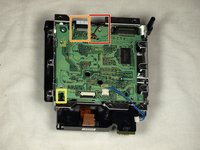
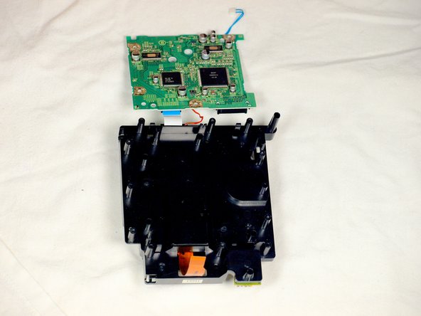
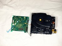
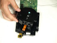
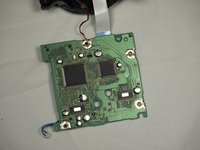
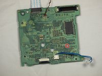
    • Rotate the assembly so that the green circuit board is facing you as shown in the first picture.

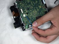
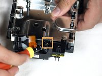
    • Flip board over so it is oriented as shown in the second picture.

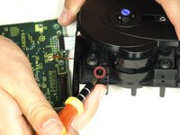
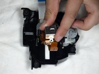
    • Using a Phillips #1 Screwdriver, turn the small knob very slightly counter-clockwise—a few degrees to, at most, one-quarter turn.

    • You can find instructions for testing to make sure your repair worked at this link.

終わりに

To reassemble your device, follow these instructions in reverse order.

26 の人々がこのガイドを完成させました。

作成者

14人の作成者と共同で作成されました。

agronbac

メンバー登録日: 10/28/09

739 ポイント

1ガイドが承認済み

チーム

Cal Poly, Team 6-2, Maness Fall 2009 Cal Poly, Team 6-2, Maness Fall 2009人のメンバー

CPSU-MANESS-F09S6G2

4 メンバー

44のガイドは作成済み

5 件のコメント

I don't understand why you have steps 11-17. In step 10, you can clearly see the board with the screw that needs adjusting. Taking apart the rest of the GameCube is utterly unnecessary. After following the guide in full, I thought, 'Why did I just dismantle all that other stuff when I didn't even NEED to?'

Once the assembly is removed from the metal covering the board, it is a simple matter to turn the screw to increase the laser strength. I did this after my initial adjustment didn't work. I ignored steps 11-17 and everything works perfectly now. My old games which simply would not load, now do. Thanks for the advice leading up to step 10 though. That part was helpful.

Johnny H - 返信

I wouldn't say it's a quarter of a turn, a few degrees clockwise do the trick. I tried a quarter of a turn the first time and it made the disk unit useless as it didn't recognise any gamecube disk.

Jaime Aluja - 返信

Thanks for the detailed pictures! I was able to get everything taken apart, and fixed the read error I was having after a couple of readjustments.

One important note: the lens screw should be turned counter-clockwise, not clockwise. A quarter turn is also likely to be too much; better to adjust a few degrees at a time and test repeatedly until the right setting is found.

gameFAQs.com has a lens calibration guide, with notes on how to reassemble the GameCube for testing without screwing everything back together.

I also agree that steps 11-17 can be skipped, as well as step 5 to remove the controller ports.

Lauren - 返信

Steps 11+ are definitely not needed and 1/4 turn is more than 200ohms, way too much. It has to be moved by a hair (almost literally), the potentiometer is extremely sensitive. And I would personally recommend some form of multimeter, as to not go turning that screw blindly.

Nicola Lahaie - 返信

Great guide, this fixed my problem. Would like to be clarified if you need to follow steps 11-17 make the power adjustment.

Héctor Sierra Montañez - 返信

コメントを追加

統計データ:

過去 24時間: 62

過去 7 日: 490

過去 30 日: 2,290

今までの合計 111,382