メインコンテンツにスキップ

このバージョンは誤った内容を含んでいる可能性があります。最新の承認済みスナップショットに切り替えてください。

必要な工具と部品

  1. この手順は未翻訳です。 翻訳を手伝う。

    : 手順 1、 3の画像 1 : 手順 1、 3の画像 2 : 手順 1、 3の画像 3
    • Use a Phillips #00 screwdriver to remove the single 4mm screw located directly to the right of the viewfinder on the back of the camera.

    • Remove the two 2mm screws from the left side panel.

    • Remove the single 3mm screw from the right side panel.

    • Remove the five 3mm screws from the bottom of the camera.

  2. この手順は未翻訳です。 翻訳を手伝う。

    : 手順 2、 2の画像 1 : 手順 2、 2の画像 2
    • Rock the two ribbon cables gently out of their sockets.

    • For more on disconnecting ribbon cables, look here.

    • Grasp and pull the white cable out of its clip with metal tweezers.

    • Remove the back panel completely.

  3. この手順は未翻訳です。 翻訳を手伝う。

    : 手順 3、 1の画像 1
    • Peel off the black plastic sheets.

    • Use the Phillips #00 screwdriver to remove the two 3mm screws holding the motherboard in place.

  4. この手順は未翻訳です。 翻訳を手伝う。

    : 手順 4、 2の画像 1 : 手順 4、 2の画像 2
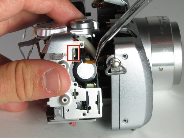
    • Remove the ribbon cable directly below the viewfinder.

    • Detach the white plastic clip from its socket with a pair of tweezers.

    • Disconnect the ribbon cable from the center of the board, near the central hole.

    • Disconnect the three ribbon cables from the top right of the motherboard, near the selector wheel. One is on the top of the board, and the other two are on the underside.

    • For more information on disconnecting ribbon cables, look here.

  5. この手順は未翻訳です。 翻訳を手伝う。

    : 手順 5、 1の画像 1
    • Remove the single 3mm ground screw attached to the right side of the camera body using the Phillips #00 screwdriver.

  6. この手順は未翻訳です。 翻訳を手伝う。

    : 手順 6、 1の画像 1
    • Use the soldering iron to desolder the connections from the motherboard.

    • For more information on desoldering, look here.

    • When soldering, avoid touching any of the other components with the soldering iron to prevent damage to the motherboard.

  7. この手順は未翻訳です。 翻訳を手伝う。

    : 手順 7、 1の画像 1
    • Remove the motherboard from the camera.

  8. この手順は未翻訳です。 翻訳を手伝う。

    : 手順 8、 2の画像 1 : 手順 8、 2の画像 2
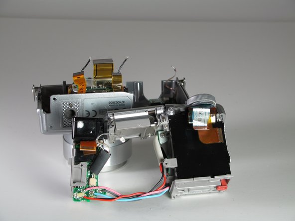
    • Remove most of the camera components from the front of the case.

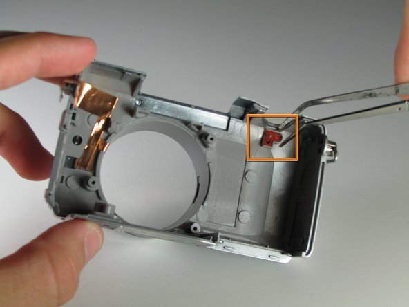
    • Remove the two 3 mm screws from the right side of the casing using a Phillips #00 screwdriver.

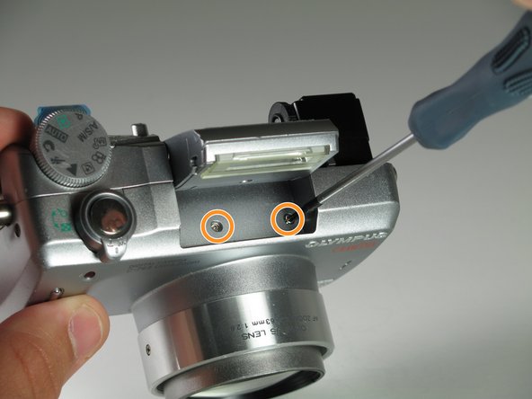
    • Pop the flash up to get access to the two body screws underneath.

    • Remove the two 3mm screws from under the flash using a Phillips #00 screwdriver.

  9. この手順は未翻訳です。 翻訳を手伝う。

    : 手順 9、 3の画像 1 : 手順 9、 3の画像 2 : 手順 9、 3の画像 3
    • Gently pull on the battery casing and the A/V ports to remove the connected components.

    • Remove the small ribbon cable, from the right side of the casing.

  10. この手順は未翻訳です。 翻訳を手伝う。

    : 手順 10、 2の画像 1 : 手順 10、 2の画像 2
    • Remove the LED circuit board.

    • Remove the single 3mm screw using a Phillips #00 screwdriver.

    • Use a pair of tweezers to remove the status LED board.

ゴール

作成者

5人の作成者と共同で作成されました。

Mason Morgan

メンバー登録日: 04/05/11

115 ポイント

6のガイドは作成済み

チーム

Cal Poly, Team 12-33, Maness Spring 2011 Cal Poly, Team 12-33, Maness Spring 2011人のメンバー

CPSU-MANESS-S11S12G33

3 メンバー

7のガイドは作成済み

0 件のコメント

コメントを追加

統計データ:

過去 24時間: 0

過去 7 日: 0

過去 30 日: 2

今までの合計 2,274