メインコンテンツにスキップ

このバージョンは誤った内容を含んでいる可能性があります。最新の承認済みスナップショットに切り替えてください。

必要な工具と部品

  1. この手順は未翻訳です。 翻訳を手伝う。

    : 手順 1、 3の画像 1 : 手順 1、 3の画像 2 : 手順 1、 3の画像 3
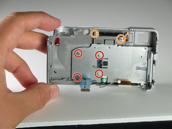
    • Remove all the screws using your Phillips #00 holding the back plate in place. This includes:

    • On the Back: Unscrew the 4mm screw to the right of the viewfinder.

    • On the Bottom:

    • Unscrew the 3mm screw in the top left corner.

    • Unscrew the four 3mm screws under the battery cover.

    • On the Right Side: Unscrew the one 3mm screw holding the right-side panel.

    • On the Left Side: Unscrew the two 2mm screws holding the left-side panel.

  2. この手順は未翻訳です。 翻訳を手伝う。

    : 手順 2、 2の画像 1 : 手順 2、 2の画像 2
    • After you remove the back cover:

    • Gently pull the two ribbon cables out of their sockets.

    • Gently disconnect the white cable.

  3. この手順は未翻訳です。 翻訳を手伝う。

    : 手順 3、 3の画像 1 : 手順 3、 3の画像 2 : 手順 3、 3の画像 3
    • Peel the black tape off the back of the LCD.

    • Using the Phillips #00 remove the four 3mm screws on the LCD bracket.

    • Remove the two 2mm screws from the top of the bracket.

    • Use a spudger to pop the LCD screen out of the camera’s backplate.

    • When the bracket comes off, the buttons from the top section may fall out of place. If this happens then put them back in the position they were in.

ゴール

2 の人々がこのガイドを完成させました。

作成者

8人の作成者と共同で作成されました。

Mason Morgan

メンバー登録日: 04/05/11

115 ポイント

6のガイドは作成済み

チーム

Cal Poly, Team 12-33, Maness Spring 2011 Cal Poly, Team 12-33, Maness Spring 2011人のメンバー

CPSU-MANESS-S11S12G33

3 メンバー

7のガイドは作成済み

0 件のコメント

コメントを追加

統計データ:

過去 24時間: 0

過去 7 日: 1

過去 30 日: 15

今までの合計 2,884