この修理ガイドは変更されています。最新の未承認バージョンに切り替えます。
はじめに
Replacing the flash assembly, includes going deep into the camera, and taking out the logic board requiring soldering and other technical aspects.
必要な工具と部品
-
-
Use a Phillips #00 screwdriver to remove the single 4mm screw located directly to the right of the viewfinder on the back of the camera.
-
Remove the two 2mm screws from the left side panel.
-
Remove the single 3mm screw from the right side panel.
-
Remove the five 3mm screws from the bottom of the camera.
-
-
-
Remove the ribbon cable directly below the viewfinder.
-
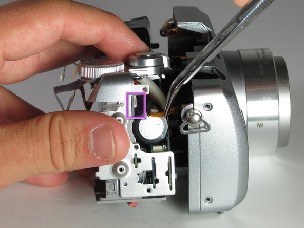
Detach the white plastic clip from its socket with a pair of tweezers.
-
Disconnect the ribbon cable from the center of the board, near the central hole.
-
Disconnect the three ribbon cables from the top right of the motherboard, near the selector wheel. One is on the top of the board, and the other two are on the underside.
-
-
-
-
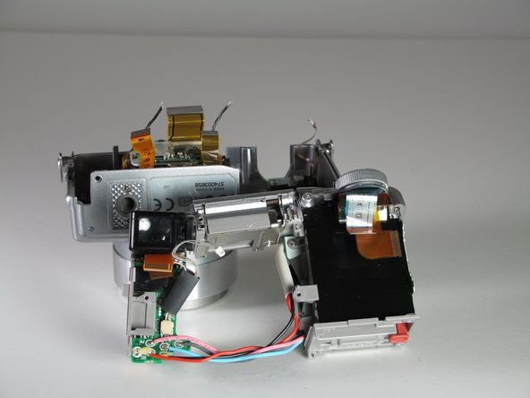
Now we remove the bulk of the cameras components from the front of the case
-
Unscrew the 2-3mm Screws from the right side of the casing
-
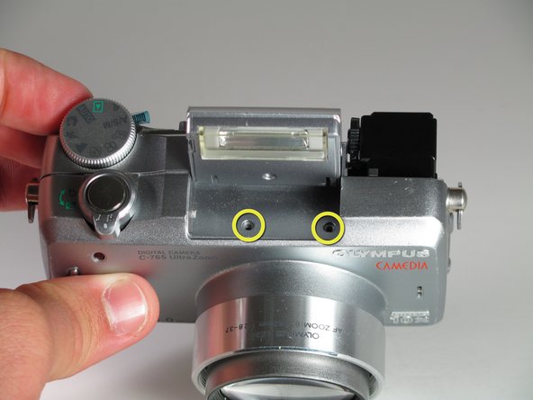
Pop the flash up, to get access to the two body screws underneath
-
Undo the 2-3mm screws
-


To reassemble your device, follow these instructions in reverse order.
To reassemble your device, follow these instructions in reverse order.
チーム

Cal Poly, Team 12-33, Maness Spring 2011 Cal Poly, Team 12-33, Maness Spring 2011人のメンバー
CPSU-MANESS-S11S12G33
3 メンバー
7のガイドは作成済み