はじめに
マイクロUSBポートは主にタブレットに充電する為に使われます。ダメージを負うとUSBケーブルに緩みが発生し接触不良の原因になります。
必要な工具と部品
-
-
画像にあるようにバッテリー下に青のプラスチック製開口ツールの先端を差し込みます。
-
-
-
バッテリーが十分に緩んだら開口ツールを使いバッテリーをデバイスから持ち上げます。
The white wire is for temperature line. What about the green wire? I have generic battery almost same size ang xapacity but it had only 3 wires, red black ang white. Green is missing
-
-
-
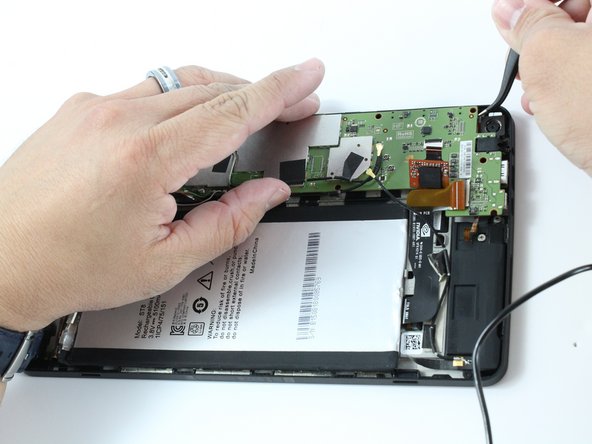
ハンダごてを使用して4本のケーブルをマザーボードから外します。
-
ワイヤーがマザーボードから外されればバッテリーはデバイスから自由に動かせます。
Where can I buy a replacement battery??
Where can I buy a replacement battery for my Nvidia tablet??
Aliexpress -[L508 3,8 V 3,7 V 5000 mAh [3565152] PLIB; polímero de iones de litio/Li-ion batería para tablet pc de autonomía, carga de dispositivos, corrección keystone automática, e-book; BL-T17 celular
Those replacement batteries only have 2 or 3 wires. Any ideas since the one on the Shield has 4 wires?
-
-
-
アングル付きピンセットを使用して黒い電源ケーブルをマザーボードから外します。引っ張ると、そのスロットからケーブルが飛び出します。
You do not need to disconnect the antenna power cable. You only need to disconnect the other 2 black power cables. Just pull the antenna out together with the Mboard.
Dave Bogan - 返信
Did you not remove the battery and disoldered its cables? Why are they still in place?
-
-
-
-
アングル付きピンセットを使用してWi-Fiアンテナをデバイスから外します
-
-
-
各スピーカーのオーディオ入力フィルムをZIF (zero insertion force) コネクターから慎重に取り外します、オレンジ色で縞模様の薄い紙のリボンがオーディオ入力フィルムです
-
ZIFコネクターの白いラッチを引いてフィルムを解放しピンセットで引き出します
-
左右のスピーカーの残るもう一方のフィルムも同じ様に解放します
How did you remove the antenna in step 10 without removing the audio input films? In this photo, the antenna is still in place. Your instructions are a complete mess!!!
-
-
-
バッテリーにスピーカーを接続させているゴールドの先端が付いた黒い電源ケーブルを取り外します。
-
さらにピンセットを使って慎重に引き上げると、電源ケーブルは簡単に外れます。
Have you not already removed these in Step 7 ???
Removing cables already removed in step 7 ???
-
-
-
ネジを外してスピーカーを取り出します。J000プラスドライバーを使います。
You only need to remove the speaker on the right of this photo, you can leave the other, longer one, in place.
Dave Bogan - 返信
Battery in place, cables soldered, antenna in place, etc, as if you haven’t done any of the previous 14 steps. What a mess…
I think what you meant was 3mm, not 30mm.
-
-
-
マザーボードをケースに固定している残りのネジを外します。
-
ネジの説明 : 長さ2.0mm、直径3.0mmの黒い小さなネジ (写真赤丸の5本)
-
ネジの説明 : 長さ4.0mm、直径2.0mmの黒くて細長いネジ (写真オレンジ丸の3本)
Mine had an additional screw on the top left corner of the motherboard. You can actually see it in this picture, directly above the left most screw.
Eric Jones - 返信
I just realized that this is the screw described in step 8, which was supposed to be removed by this step. Guess I can't follow instructions.
-
-
-
ピンセットを使ってマザーボードの先端を少しだけ持ち上げて下さい。
-
マザーボードをケースから取り外す前に、リアカメラとマザーボードを接続する銅線をピンセットを使って接続を外します。
Congratulations, you’ve just ripped the connector for the front camera when you lifted the motherboard out. The other speaker needs to be removed BEFORE lifting the motherboard, and the front camera, which is glued in, loosened so it lifts out with the motherboard.
You can also lift the rear facing camera out. It’s held in only by some double sided tape. This will be necessary to plug it back in anyways.
Dave Bogan - 返信
I wish I had read the users’ comments before attempting this repair….
-
-
-
ハンダごてを使って、マイクロUSBポートをマザーボードから外します。
-
これでマイクロUSBポートはマザーボードから解放されます。
You will need to plug in both cameras first and install them together with the Mboard as the connectors are on the underside.
Dave Bogan - 返信
BIG NOTE: The entire bottom surface of the usb port is soldered down. You must first desolder the 5 contacts then heat the entire port until it comes loose.
Dave Bogan - 返信
How are we supposed to desolder the entire port with a soldering iron alone, as listed in the Tools Section ???? Also, even if I remove the USB port, do I not need a replacement one? Where is it in the list of required parts? The worst iFixIt guide ever !!!
There is no
Use a soldering iron to desolder the Micro USB Port from the motherboard.
Because the port is soldered at all four corners and the base and the connectors; the only way to do this is a heat gun built specifically for desoldering. Please, Ryan Butler, do not mislead people so that they ruin their mainboards.
To those reading this, buy a heat gun. If said heat gun costs more than a tablet from 2015, buy a new tablet and toss the old one. NVIDIA did not build this thing for home repair. This is disposable Android tech at its finest.
This component is in a minefield of other transistors and plastic components, so you must be careful. The connections and copper love to de-tin or delaminate.
Again, Ryan Butler's last step (step 20) is pure crap. Buy a heat gun.
To resolder the port, the contacts must have copper under them and solder on them or you're boned.
-


組み立て直す時は逆の順序で組み立てて下さい。
組み立て直す時は逆の順序で組み立てて下さい。
5 の人々がこのガイドを完成させました。
以下の翻訳者の皆さんにお礼を申し上げます:
100%

これらの翻訳者の方々は世界を修理する私たちのサポートをしてくれています。 あなたも貢献してみませんか?
翻訳を始める ›

チーム

iFixit, Team 1-1, Weber Winter 2016 iFixit, Team 1-1, Weber Winter 2016人のメンバー
FIX-WEBER-W16S1G1
4 メンバー
37のガイドは作成済み
12 件のコメント
Where I can find a micro UBS port for Nvidia shield tablet ?
Micro usb -B, Amazon.
it's a standard form factor, just check ebay
It might be cheaper to solder a new one. I would compare prices, and decide if the price is worth soldering. If you want experience in soldering, go the solder route. Refining this skill will help later if you need to solder anything else.
To remove the mainboard, it’s not necessary to remove the battery. I would strongly recommend to keep it in place.
De-soldering is sufficient.
Thanks for the tip, I’m about to change the port in mine.
This guide doesn’t mention what type of adhesives will work for reassembly?
How can I fix the USB port of my Nvidia Shield k1 any idea is better to replace a new port or solder .
Manque: Tresse à dessouder, soudure laiton (fils batterie + fixation Micro USB) + pâte a braser, fer à souder CMS (air chaud) (pour pin Micro USB)
Manque: Micro usb port neuf
Inutile: (3,4,5) juste dessouder les 4 fils, ne pas essayer de la décoller, ou utiliser un dissolvant si autre besoin de réparation.
Erreur : 7, le câble noir n'est pas un câble d'alimentation, pas besoin de le déconnecter, voir étape 8 et 14
Dernière étape, il reste le plus difficile, ressouder un port USB neuf sur la carte mère, facile, souder les 5 pins beaucoup moins et surtout quasi impossible avec un fer à souder standard, peut être avec l'aide d'un microscope ?
Il faut un poste soudure CMS et de la pate à braser que l'on aura déposer sur les pins avant de fixer le port usb sur la carte mêre.
Tuto Utile pour les propriétaires de tablette ayant le matériel et le savoir faire en électronique, inutile pour les autres, entre le savoir faire et le prix de l'investissement matériel. Cherchez un professionnel et compter 60-80 euros.
Thanks for the tips. I recommend using a de-soldering tool instead of braid though. It’s basically a spring loaded syringe that works backwards, sucking up the molten solder.
I see that the micro usb's weldings are immediately accessible, it is possible think to weld a wireless receiver?
beware the very small ribbon cable from the bottom speaker under the tape near to the micro USB port - I was very careful when peeling back the tape but I did not realise the last corner covered that ever so this piece connected at 90 degrees horizontally and it so easiy tore through. Now I have to figure out how to fix that as it appears to be glued into the speaker :( I know this is years later but any suggestions for that are appreciated - and I will look through the site for the same