メインコンテンツにスキップ

このバージョンは誤った内容を含んでいる可能性があります。最新の承認済みスナップショットに切り替えてください。

必要な工具と部品

  1. この手順は未翻訳です。 翻訳を手伝う。

    : 手順 1、 3の画像 1 : 手順 1、 3の画像 2 : 手順 1、 3の画像 3
    • Make sure the phone is off.

    • Use the T5 screwdriver to remove the two 8.6mm long screws, located at the bottom of the phone. (Head size is 2.5mm)

  2. この手順は未翻訳です。 翻訳を手伝う。

    : 手順 2、 2の画像 1 : 手順 2、 2の画像 2
    • Use the smallest Torx screwdriver or another small poking tool and push into the hole on the SIM card slot. The plastic SIM protective piece should pop out quite easily.

    • Put that plastic piece aside.

  3. この手順は未翻訳です。 翻訳を手伝う。

    : 手順 3、 2の画像 1 : 手順 3、 2の画像 2
    • Once both screws on the bottom are removed, and the plastic SIM protective piece is removed, gently push on the outside of the screen.

    • The screen should become separated using little force. And should like the pictures shown once complete.

  4. この手順は未翻訳です。 翻訳を手伝う。

    : 手順 4、 2の画像 1 : 手順 4、 2の画像 2
    • This step may be easier to remove the battery first, but it is not mandatory.

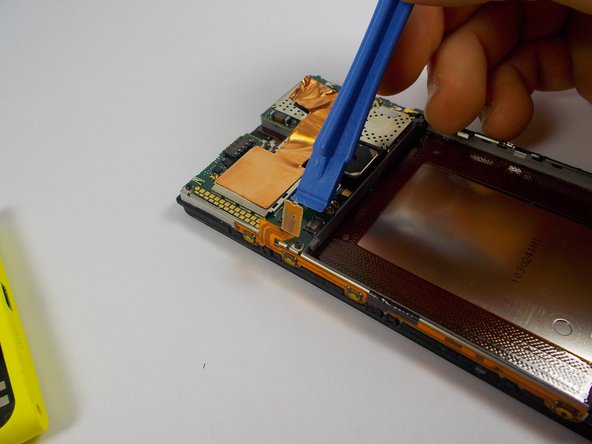
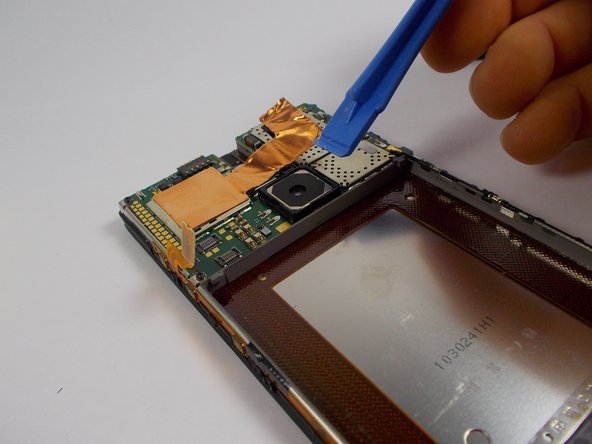
    • Place the spudger tool or flat plastic tool on top of the ribbon cable to avoid damaging it when prying up on the metal clip.

    • Use a plastic opening tool, or gently use a small metal flat-head screwdriver to pry up the metal clip. (It is recommended to use a plastic tool; However, if the opening tool does not work or fit into the small opening underneath the clip, use the flat-head.)

  5. この手順は未翻訳です。 翻訳を手伝う。

    : 手順 5、 2の画像 1 : 手順 5、 2の画像 2
    • Once the metal clip is removed, gently pry up on the ribbon cable connection, located underneath the metal clip you have just removed.

  6. この手順は未翻訳です。 翻訳を手伝う。

    : 手順 6、 2の画像 1 : 手順 6、 2の画像 2
    • Prerequisite step: Back panel removal

    • Use the T4 torx screwdriver to remove the 3mm screw (diameter of the head is 1.5mm) fastened to the metal clip, holding the battery in place.

  7. この手順は未翻訳です。 翻訳を手伝う。

    : 手順 7、 3の画像 1 : 手順 7、 3の画像 2 : 手順 7、 3の画像 3
    • Using the plastic opening tool, pry up on the metal clip holding the battery in place.

    • Completely remove the clip.

  8. この手順は未翻訳です。 翻訳を手伝う。

    : 手順 8、 3の画像 1 : 手順 8、 3の画像 2 : 手順 8、 3の画像 3
    • Use a plastic opening tool. Start on the right, and gently lift up on the copper strip.

    • You do not have to completely remove the copper strip, only enough so that the connection to the battery is visible.

  9. この手順は未翻訳です。 翻訳を手伝う。

    : 手順 9、 1の画像 1
    • Use a plastic opening tool or spudger, and gently lift up on the connective piece.

  10. この手順は未翻訳です。 翻訳を手伝う。

    : 手順 10、 3の画像 1 : 手順 10、 3の画像 2 : 手順 10、 3の画像 3
    • Use a plastic opening tool at the bottom of the battery and gently lift.

    • The battery should lift out easily.

  11. この手順は未翻訳です。 翻訳を手伝う。

    : 手順 11、 3の画像 1 : 手順 11、 3の画像 2 : 手順 11、 3の画像 3
    • Prerequisite guides: Back panel removal, Battery Removal

    • Use the plastic opening tool to gently lift up on the connective piece attached to the volume, camera, and power button strip.

  12. この手順は未翻訳です。 翻訳を手伝う。

    : 手順 12、 3の画像 1 : 手順 12、 3の画像 2 : 手順 12、 3の画像 3
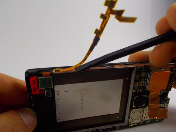
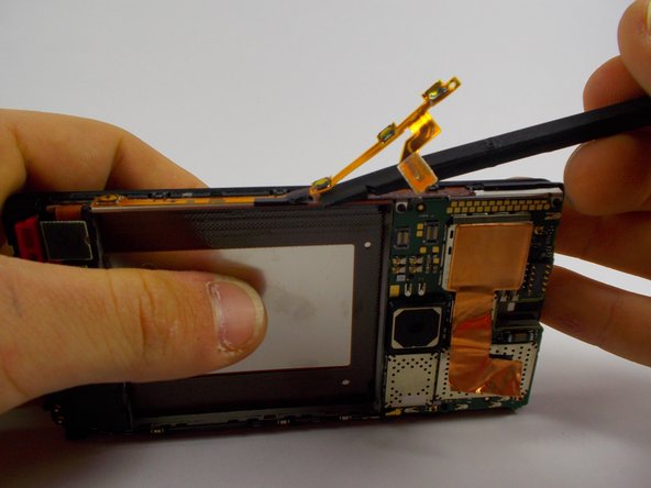
    • Flip the front panel on its side with the strip you are working on facing upward.

    • Use a spudger tool and starting at the top, gently pry the button sensors up.

    • Slide the tool underneath the strip and pry up the next button sensor.

    • Do this down the line until the strip becomes completely detached.

  13. この手順は未翻訳です。 翻訳を手伝う。

    : 手順 13、 1の画像 1
    • The power strip should look like this fully detached.

ゴール

6 の人々がこのガイドを完成させました。

作成者

3人の作成者と共同で作成されました。

Jonathan

メンバー登録日: 10/31/14

1,492 ポイント

4のガイドは作成済み

チーム

UMass Dartmouth, Team 4-2, Miles Fall 2014 UMass Dartmouth, Team 4-2, Miles Fall 2014人のメンバー

UMASSD-MILES-F14S4G2

2 メンバー

7のガイドは作成済み

0 件のコメント

コメントを追加

統計データ:

過去 24時間: 0

過去 7 日: 0

過去 30 日: 13

今までの合計 5,658