メインコンテンツにスキップ

Nokia 8390 Motherboard Replacement

必要な工具と部品

  1. Nokia 8390 Motherboard Replacement, Back Cover: 手順 1、 1の画像 1
    • Locate the button on the bottom of the back cover.

  2. Nokia 8390 Motherboard Replacement: 手順 2、 3の画像 1 Nokia 8390 Motherboard Replacement: 手順 2、 3の画像 2 Nokia 8390 Motherboard Replacement: 手順 2、 3の画像 3
    • Depress the button with your finger.

    • While the button is depressed, slide the back cover off of the phone.

  3. Nokia 8390 Motherboard Replacement, Outer Case: 手順 3、 3の画像 1 Nokia 8390 Motherboard Replacement, Outer Case: 手順 3、 3の画像 2 Nokia 8390 Motherboard Replacement, Outer Case: 手順 3、 3の画像 3
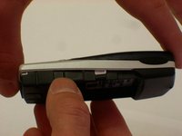
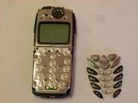
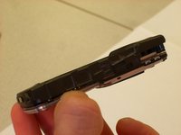
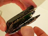
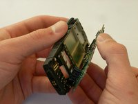
    • Grasp the top and bottom of the front cover.

    • Grasp the phone body with your other hand.

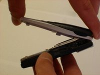
    • Lightly pull the casing off of the phone.

  4. Nokia 8390 Motherboard Replacement, Keypad: 手順 4、 3の画像 1 Nokia 8390 Motherboard Replacement, Keypad: 手順 4、 3の画像 2 Nokia 8390 Motherboard Replacement, Keypad: 手順 4、 3の画像 3
    • Lightly peel the keypad off of the phone.

  5. Nokia 8390 Motherboard Replacement, Motherboard: 手順 5、 3の画像 1 Nokia 8390 Motherboard Replacement, Motherboard: 手順 5、 3の画像 2 Nokia 8390 Motherboard Replacement, Motherboard: 手順 5、 3の画像 3
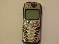
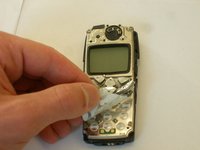
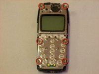
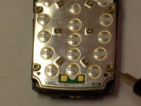
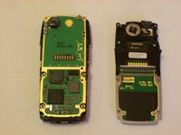
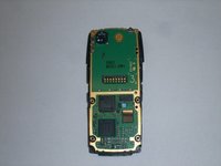
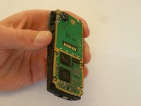
    • Locate the six star-shaped screws on the phone.

    • Note: There are two on the bottom end, two in the middle, and two on the top end.

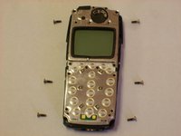
    • Remove these screws using the screwdriver.

  6. Nokia 8390 Motherboard Replacement: 手順 6、 3の画像 1 Nokia 8390 Motherboard Replacement: 手順 6、 3の画像 2 Nokia 8390 Motherboard Replacement: 手順 6、 3の画像 3
    • Grab the top and bottom of the phone casing.

    • Carefully pull the motherboard apart from the bottom casing.

    • The circuit board should be divided into two parts.

  7. Nokia 8390 Motherboard Replacement: 手順 7、 3の画像 1 Nokia 8390 Motherboard Replacement: 手順 7、 3の画像 2 Nokia 8390 Motherboard Replacement: 手順 7、 3の画像 3
    • Grab the top and bottom of the remaining casing.

    • Carefully pull apart the casing from the circuit board.

  8. Nokia 8390 Motherboard Replacement: 手順 8、 1の画像 1
    • The circuit board should be divided into three parts, completely separate from the back casing, as shown.

終わりに

To reassemble your device, follow these instructions in reverse order.

作成者

4人の作成者と共同で作成されました。

Clinton

メンバー登録日: 10/22/12

57 ポイント

7のガイドは作成済み

チーム

Clemson, Team 14-5, Benson Fall 2012 Clemson, Team 14-5, Benson Fall 2012人のメンバー

CLEM-BENSON-F12S14G5

3 メンバー

16のガイドは作成済み

0 件のコメント

コメントを追加

統計データ:

過去 24時間: 0

過去 7 日: 0

過去 30 日: 0

今までの合計 481