はじめに
このガイドを参照して、Nintendo Switch Lite デジタイザを交換します。この修理ではJoystickやボタンの取り外しは必要ありませんが、これらのコンポーネントを外すと、修理はより簡単に進みます。
Switch LiteはJISネジを使用していますが、急なときはプラス(PH)ドライバーでも対応できます。iFixitのプラスビットはJIS規格のネジと相互互換性があるように設計されているので、ネジを剥がさないように十分注意してください。
注意: このガイドは、デジタイザーのみを対象としています。LCDが動作しなくなった場合は、デジタイザではなく、LCDを交換する必要があるかもしれません。スクリーンアセンブリ(デジタイザに取り付けられているLCD)を交換する場合は、 こちらのガイド を参照してください。
ご注意:この修理ガイドでは、シールドプレートとヒートシンクを取り外します。両方のコンポーネントとCPU上に残っている放熱グリスを除去して、シールドプレートとヒートシンクを再インストールする前に、放熱グリスを新しく塗布してください。
必要な工具と部品
-
-
Y00ドライバーを使って、バックパネルを固定している6.3mmネジを4本外します。
-
-
-
プラスドライバーもしくはiFixit PH000ドライバー で、バックパネルを固定している次のネジを外します。
-
デバイス上部の長さ3.6mmネジー2本
-
デバイス下部の長さ3.6mmネジー2本
I accidentally stripped the back screw and now I can't open it. I removed all the other screws. What should I do?
-
-
-
デバイス下部の左側スピーカーグリルの内側に、開口ツールを差し込みます。
-
開口ツールをひねって、バックパネルを固定しているクリップを外します。
-
-
-
プラスドライバーもしくは iFixit PH 000ドライバーを使って、次のネジを4本外します。
-
長さ3.1 mmネジー3本
-
長さ4.5 mmネジー1本
There are four screws instead of three mentioned
With how easy it seems to be to do serious damage with the next few steps, I figured I'd say that realistically you can skip steps 9-13 when doing this repair. While they provide a bit of extra security by disconnecting the battery, the left stick is completely accessible and replaceable without touching the heat shield or anything underneath (And steps 17 and 18 disconnect power from the daughter board regardless).
i stripped a &&^&^$^ screw
Well I actually removed the screw right next to the 4.5 screw. I did not realize it till my son showed me why the plate wouldn't release. Ha ha, it's funny now but yeah not a big deal. I could have bent it badly assuming I took all screws out though. For anyone reading this before going in. 👍
Toastninja - 返信
-
-
-
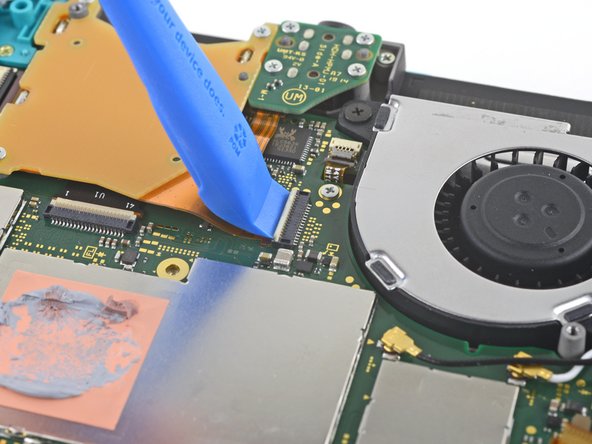
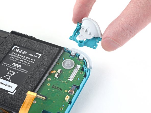
開口ツールもしくは爪先で、マザーボードの相互接続ケーブルのZIFコネクタに付いている小さなヒンジ状の固定フラップを跳ね上げます。
The clip broke off when trying to remove this cable. Audio only works through headphones and the display now won’t turn on after the clip broke. Does anyone know where I could get a clip or how I could fix it without it?
Mi è successa la stessa cosa è non so come ripararla! Chissà se c’è un modo!
-
-
-
ピンセットでマザーボード上のコネクタから、相互接続ケーブルをスライドして外します。
I turned the unit off beforehand, I used tweezers just like the instructions said (ifixit branded) , my device sparked and now it won’t turn back on
The flap came off is it important or is there a way t fix it?
We're you able to get it working without the white flap? My screen is not working after putting it back together and i noticed this white flap was falling off
Did you get it working without the white flap? Everything on the switch works fine except for audio going through headphones and the display not turning on.
do not use metal sharp pointed tweezers! you will rip your ribbon cable. Use the inside of a Bic type pen or something else dull and plastic to pull the cable away by putting the pen part where the first bend is.
-
-
-
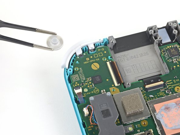
スパッジャーの先端を使って、マザーボード上のソケットからバッテリーコネクタをこじ開けて、接続を外します。
Caution the connector may not be properly soldered onto the motherboard. For me it snapped off the pins and now have to find a place to get that fixed if even possible. may have bricked it.
Yup, broke the connector right off the motherboard. Thanks, ifixit -_-
I backed out when I reached this point. I couldn't risk damaging it. Do u just need to pull it up? Did you mean that it might have been soldered shut below?
Jannalyzer - 返信
You should just need to pull straight up, but make sure you’re pulling on the wires or the gray plug—do not pull on the black socket or it can snap off of the motherboard.
With how easy it seems to be to do serious damage at this point, I figured I'd say that realistically you can skip steps 9-13 when doing this repair. While they provide a bit of extra security by disconnecting the battery, the left stick is completely accessible and replaceable without touching the heat shield or anything underneath (And steps 17 and 18 disconnect power from the daughter board regardless).
just broke my connector... ifixit PLEASE put a warning on how fragile the solder on this connector is.
Note for this step, you do not need to apply a lot of force. I used two tools here: small screwdriver to hold down the black base, and one side of fine-tipped tweezers to get under all 3 wires. Gently, push down on the tweezers to push the wires upwards, which should force the gray connector up and off the base. It did not take a lot of force. Take your time and it will be fine. Again, like others have said, do NOT pull or pry up the black base.
-
-
-
スパッジャーの平面側先端もしくは爪先で、ファンに軽く接着剤で固定されたフォームを慎重に剥がします。
When reassembling, the foam may fold down between the fan and heatsink, blocking airflow. Gently lift the foam back up on top of the fan. The adhesive film should hold the foam together.
Kean Stump - 返信
Is removing the heat sink absolutely necessary?
It’s not necessary, but it makes it much easier to remove and replace the game card reader, since the heat sink partially covers the connector.
Not really…….. I never remove it. It slides out quite easily once disconnected.
Alan Sears - 返信
-
-
-
プラスドライバーもしくは iFixit PH 000ドライバーを使って、ヒートシンクをマザーボードに固定している、長さ3mmネジを3本外します。
Non le tre ventole ma le tre viti
Grazie per avercelo segnalato! Ho apportato la modifica. iFixit è una wiki, quindi ogni utente può modificare le pagine: se trovi altri errori in futuro, sentiti libero di fare la modifica tu stesso!
-
-
-
スパッジャーもしくは爪先で、ヒートシンクを持ち上げて、マザーボードから外します。
16.5 remove cartridge / headphones jack……….
My kit did not come with thermal paste..
-
-
-
JIS000ドライバーもしくはiFixit PH000ドライバーを使って、右側トリガーボタンアセンブリをマザーボードに固定している、長さ4.5mmネジを2本外します。
I think a whole step to remove the game card reader and speaker jack was skipped here…
yes, just found that sadly these comments do not show unless we click on the , which is unhelpful
also, you need to remove the left trigger button
-
-
-
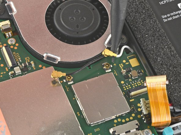
スパッジャーの先端を使って、マザーボード上のソケットから黒いアンテナケーブルをまっすぐ持ち上げて外します。
-
白いアンテナケーブルについても同じ作業を繰り返します。
-
-
-
ピンセットを使って、マザーボード上のコネクタからファンケーブルをスライドして外します。
There’s a step missing after this to remove the screws that hold the orange game cartridge slot. Those 7 screws have to be undone and the ribbon unclipped first before moving on to the next step.
Good Looking out!
-
-
-
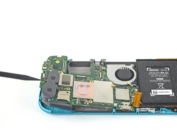
開口ツールもしくは爪先を使って、スクリーンケーブルのZIFコネクタ上の小さなヒンジ付き固定フラップをこじ開けます。
skipped a step or two about removing the golden piece in the photo above, and the other little board
If I broke the clasp on the ZIF connector can I elec tape it down?
What did you do to fix it if the ZIF connector broke?? Mine did too and I worry that is why the screen won’t turn on now
Missing the card reader + audio jack board removal. Just remove the 4 screws around the audio jack + 3 screws around the card reader and disconnect the ZIF connector from the motherboard.
-
-
-
-
開口ツールもしくは爪先で、デジタイザケーブルのZIFコネクタにある、小さなヒンジ付き固定フラップを跳ね上げます。
-
-
-
JIS000ドライバーもしくはiFixit PH000ドライバーで、マザーボードを固定している次の6本のネジを外します。
-
長さ3.1 mm ネジー3本
-
長さ4.5mm ネジー3本
how to get the c port off
When re-assembling, be sure the fan cable (step 25) is completely pulled through prior to tightening the screw that’s right next to it.
-
-
-
ピンセットもしくは指先で、左側スピーカーケーブルをまっすぐ持ち上げて、ドーターボード上のソケットから外します。
pulled from the connector, not the wires, and ended up ripping them off the connector anyways since it encountered tension from the other end (the gray chamber on the left)
consider doing step 15 before pulling the wire, just in case.
Why even disconnect this cable. Not worth the risk leave it connected to daughter board.
while doing this I ripped the pad on the circuit board off. Should i risk trying to repair it or should i just try to go without the speaker???
I also accidentally ripped off the connector, disabling the left speaker. However, that will not break any functionality of the switch. The right speaker works just fine on its own (just remember to turn the audio to mono in system settings) and I was successfully able to replace the joystick. Although the audio quality is a little bit depleted, you barely notice it if you turn up the volume a little, and I think being able to actually MOVE FORWARD in my games is a better plus than having louder, stereo, audio.
Went to pull the speaker connector and it pulled right off the motherboard. Would not come loose.
I'm gonna echo what others said here and suggest that you skip this step. After you complete Step 15, you can just move the speakers enough with your fingers to complete Step 26, which involves a screw half underneath it.
Regarding the ribbon cable in Step 17 & Step 18, you can honestly use your fingers if they're small enough. The ribbon cable is wide enough for you to press down on it a little and slide it out bit by bit.
Overall, this makes the disassembly and eventual reassembly process easier and lets you avoid running the risk of damaging or completely tearing out the wires, like I almost did.Removing the screw from 37 is enough to give you space to remove the board, I honestly think you shouldn't try to remove this connector.
Unfortunately, I had to reinstall multiple daughterboards on the same Switch Lite. I strongly recommend orienting your straight tweezers with ridges (like the ones in the picture) perpendicular to the device. Grab the plastic connector with the tip of the tweezers from the top. It makes inserting and removing this connection significantly easier.
-
-
-
ピンセットを使って、ドーターボード上のコネクタから左側ジョイスティックケーブルをスライドして外します。
The connector for my left joystick broke. Is there a way to fix it?
How badly did it broke?
-
-
-
JIS000ドライバーもしくはiFixit PH 000ドライバーを使って、左側トリガーボタンアセンブリを固定している4.5mmネジを2本外します。
-
-
-
JIS000ドライバーもしくはiFixit PHドライバーを使って、次のネジを4本外します。
-
長さ4.5mmネジー2本
-
長さ6 mmネジー2本
The two 4.5 mm screws were very difficult to remove here and ended up getting stripped. I CANNOT remove them, help!
-
-
-
指先でドーターボードを持ち上げて、本体から取り出します。
Stop here if repairing Switch Lite for joycon drift. After removing daughter card you can see the bottom of the joystick. This thin metal actually bends during use causing bad connection of joystick. If you cut out a business card the same size as the joycon and put it on the bottom of the joystick it gives the metal enough backing to fix the issue. I used two layers with just a small bit of glue stick to adhere it. Put it all back together and you will find your issue is fixed.
-
-
-
スパッジャーの平面側先端を使って、ジョイスティックを持ち上げます。
-
指先でジョイスティックを摘んで取り出します。
During reassembly when putting the screws back in, slowly turn them CCW until you feel it drop into its thread. You will never crossthread them by doing this.
-
-
-
JIS000ドライバーもしくは iFixit PH 000ドライバーを使って、次の4本のネジを外します。
-
2.5 mmネジー3本
-
6 mmネジー1本
-
-
-
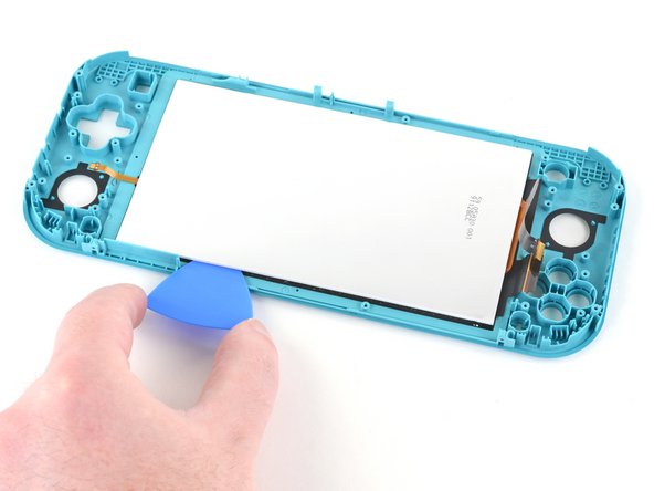
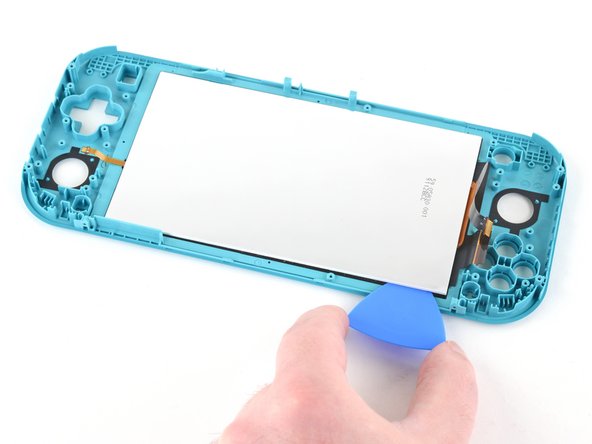
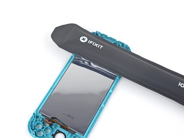
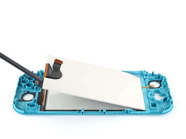
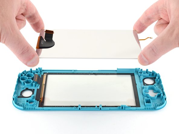
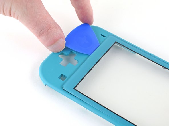
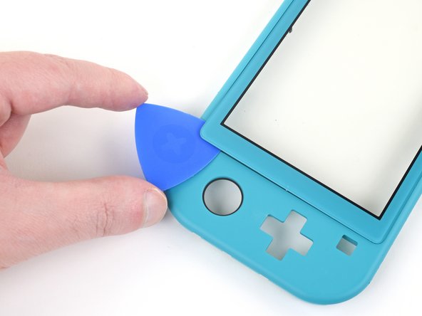
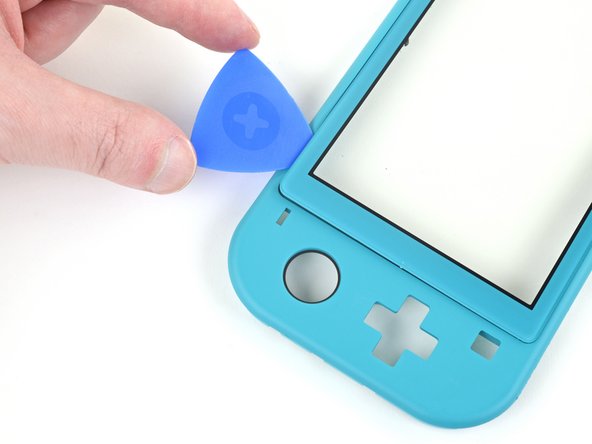
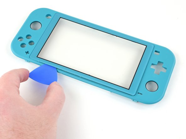
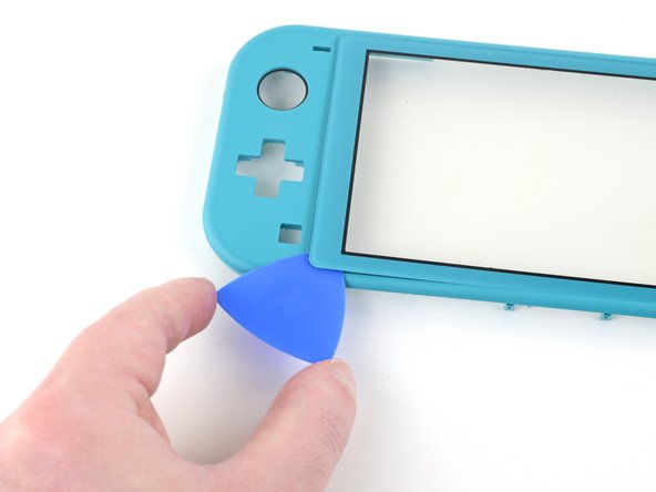
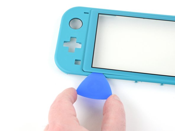
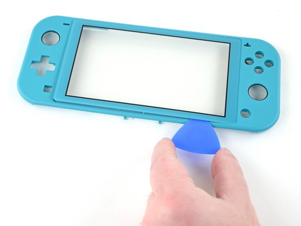
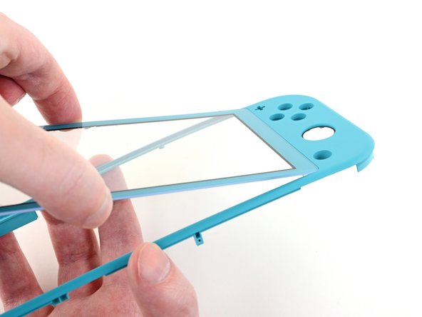
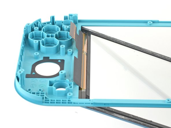
デジタイザの右側をフレームに対して45度の角度まで持ち上げて、外します。
-


このデバイスを再組み立てするには、インストラクションを逆の順番に従って作業を進めてください。
e-wasteを処理する場合は、認可済みリサイクルセンターR2を通じて廃棄してください。
修理が上手く進みませんか?ベーシックなトラブルシューティングのページを参照するか、Nintendo Switch Liteのアンサーコミュニティに尋ねてみましょう。
このデバイスを再組み立てするには、インストラクションを逆の順番に従って作業を進めてください。
e-wasteを処理する場合は、認可済みリサイクルセンターR2を通じて廃棄してください。
修理が上手く進みませんか?ベーシックなトラブルシューティングのページを参照するか、Nintendo Switch Liteのアンサーコミュニティに尋ねてみましょう。
16 の人々がこのガイドを完成させました。
以下の翻訳者の皆さんにお礼を申し上げます:
100%

Midori Doiさんは世界中で修理する私たちを助けてくれています! あなたも貢献してみませんか?
翻訳を始める ›

4 件のコメント
Great guide, but quick tip when removing the screen. There are two pieces of the screen sandwiched together and when I took mine apart, these two pieces came unstuck and ruined the screen itself. The digitizer was fine, but the LCD came apart. So make sure the opening pick gets under both of these parts rather than just the reflective back.
I bought this Switch Lite with a broken LCD to repair and sell, so the screen was already blown out, but I had the same issue. The LCD was still connected to the digitizer and it actually peeled the LCD apart. As I said earlier, the LCD was already broke so it wasn’t a big issue, but I would of been fairly angry if it hadn’t of been.
it looks like it might be possible to do steps 1 - 10, then step 28, then steps 66 onwards, and reverse to reassemble, the guide isn’t clear why it would be required to do a full tear down, is there something that would make this method not work or more likely to cause further damage, if I’m just switching out the digitizer, pun intended.. :) ?
Were I to guess, I would say that the full teardown guide is meant to apply to any, and all, scenarios, regardless of any unmentioned issues that a user may have.
Another possibility is that if a user has a damaged digitizer from a drop, or other type of impact(s); then by performing a full teardown, they may discover other elements in need of repair.
All my screws got stripped any ideas on how to remove?
Almost A Mammal - 返信
A Y0 screwdriver seemed to work better for me.
Tommy Morrill - 返信
What type of screw driver do I use to un screw the screws and which way
Luca Capito - 返信
Y 0.6 was all I had but it seemed to fit perfectly
Trevor - 返信