メインコンテンツにスキップ

Nintendo DSi Motherboard Replacement

アーカイブされたガイド
このガイドは将来的な使用のためにのみ保存されてます。ご自身の修理作業には更新バージョンをご利用ください。

必要な工具と部品

  1. 注意: 手順 1-2 は、作業進行中としてマークされている ガイド から引用されています。

    Nintendo DSi Motherboard Replacement, Battery: 手順 1、 1の画像 1
    • Loosen the two screws on the battery panel. Then lift the panel up to remove it.

  2. Nintendo DSi Motherboard Replacement: 手順 2、 1の画像 1
    • L Button.

    • Top of the battery pack.

    • To remove the battery pack, place your fingernail or a spudger at the top of the battery near the L button. Gently lift the battery out.

    That's great. WHAT ABOUT THE THREE OTHER SCREWS KEEPING THE BACK ON!?

    tekgeekster - 返信

  3. Nintendo DSi Motherboard Replacement, Lower Case Assembly: 手順 3、 2の画像 1 Nintendo DSi Motherboard Replacement, Lower Case Assembly: 手順 3、 2の画像 2
    • Two screws are hidden underneath two rubber feet highlighted in red.

    • Use the tip of a spudger to pry the rubber feet out of the lower case.

    • Depending on the age of your device, the rubber feet may crumble apart as you pry them out. If so, use a fine-tipped tool to scrape out any stuck pieces of rubber.

    One of the feet did break on me, tweezers came in handy for picking it out

    Willie Narvaez - 返信

    I unfolded and sharpened a paperclip. You can use that to stab and hook the rubber without tearing it, as the rubber is thick enough to reseal when reinserted.

    Keegan Andersen -

    Nasty, broke my spudger and the feet in this step.

    TimedIn - 返信

  4. Nintendo DSi Motherboard Replacement: 手順 4、 1の画像 1
    • Remove the following screws securing the lower case to the body of the DSi:

    • Six 5.2 mm Phillips #00 screws.

    • One 2.7 mm Phillips #00 screw.

    Impossible d'enlever les vises… trop serré! comment faire?

    evrobert03 - 返信

    i can't get the screw by the gamecard slot out, PH#00 is too small and PH#0 is too big

    Iblowup - 返信

    same problem here. maybe try a JIS?

    darth mango -

  5. Nintendo DSi Motherboard Replacement: 手順 5、 3の画像 1 Nintendo DSi Motherboard Replacement: 手順 5、 3の画像 2 Nintendo DSi Motherboard Replacement: 手順 5、 3の画像 3
    • Insert the spudger in between the lower casing and lower panel near the top right corner of the DSi.

    • Carefully run the spudger along the edge of the outer casing, creating an opening between the body and the casing.

    • Continue running the spudger around the body of the DSi until the majority of the lower case has been separated.

  6. Nintendo DSi Motherboard Replacement: 手順 6、 2の画像 1 Nintendo DSi Motherboard Replacement: 手順 6、 2の画像 2
    • Carefully lift the lower casing from its bottom edge.

    • The lower case is still attached to the motherboard by the volume and SD board cable highlighted in red. Do not try to completely remove the lower case of the DSi yet.

    • Pry the volume and SD board cable up from its socket on the motherboard using a spudger.

    • Once the cable is completely removed, then you may take off the entire outer casing.

  7. Nintendo DSi Motherboard Replacement, Wi-Fi Board: 手順 7、 1の画像 1
    • Pull the Wi-Fi board away from the motherboard by its edge closest to the headphone jack.

  8. Nintendo DSi Motherboard Replacement: 手順 8、 1の画像 1
    • Pry the Wi-Fi antenna connector straight up from its socket on the Wi-Fi board.

    After reassembling it, I switched my Nintendo DSi xl On and only the blue power light, is on after that it doesn't respond any more, except while charging it blinks

    Phillips - 返信

  9. 注意: 手順 9-10 は、作業進行中としてマークされている ガイド から引用されています。

    Nintendo DSi Motherboard Replacement, Disconnecting Nintendo DSi Battery Board: 手順 9、 1の画像 1
    • Flip up the black latch and disconnect the D-Pad/Power Button ribbon cable.

  10. Nintendo DSi Motherboard Replacement: 手順 10、 3の画像 1 Nintendo DSi Motherboard Replacement: 手順 10、 3の画像 2 Nintendo DSi Motherboard Replacement: 手順 10、 3の画像 3
    • The power connector (with red and black wires) is difficult to remove without damaging it, unless you take a moment and understand how it works. Look at all of the photos for this step before continuing.

    • The connector is two pieces -- a white "male" piece (connected to the wires), and a beige "female" part (soldered to the main board).

    • There is a small "notch" in the female part, to give you a place to insert a small flat-head screwdriver. Put the corner of your screwdriver in there, and twist it gently to push the white part up (away from the main board). Do not try to pull it to the right (towards the battery board).

    • If it does not lift easily, try again with a smaller screwdriver. You might be pulling the female connector off the board, which will be difficult to repair.

  11. Nintendo DSi Motherboard Replacement, Disconnecting (Top) Nintendo DSi Motherboard cables: 手順 11、 2の画像 1 Nintendo DSi Motherboard Replacement, Disconnecting (Top) Nintendo DSi Motherboard cables: 手順 11、 2の画像 2
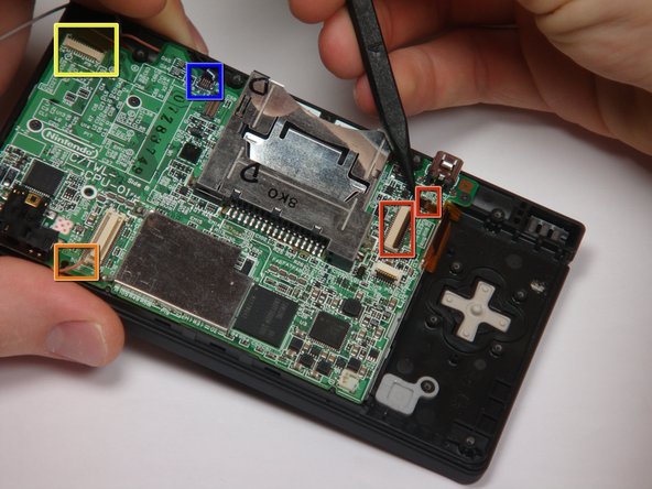
    • If you have not already done so, disconnect the two bottom-LCD ribbon cables from the main board by prying up the black latches and pulling the cable out to the side.

    • The ribbon cable (marked in blue) for the touch screen is particularly thin and fragile; be careful to avoid bending it more than necessary.

    • Flip up the latch and remove the touch screen cable.

    • Flip up the latch and remove the top-screen ribbon cable.

    • Pry up on the orange cable to disconnect it from the main board, much like the antenna cable on the Wi-Fi module.

    • Do not pull on the orange cable that connects to the bottom of the motherboard.

  12. Nintendo DSi Motherboard Replacement, Motherboard: 手順 12、 2の画像 1 Nintendo DSi Motherboard Replacement, Motherboard: 手順 12、 2の画像 2
    • Remove 4 Phillips screws from the board.

    • Lift the main board from the bottom end and flip it over to reveal the last connector.

    • Keep the main board fairly close to the case, making sure not to damage the last ribbon cable holding it in place.

  13. Nintendo DSi Motherboard Replacement: 手順 13、 1の画像 1
    • Disconnect the ribbon cable by gently using a plastic opening tool to flip up the black connector latch. The cable should easily slide out from the connector.

    • The motherboard should now be free from the rest of the device.

終わりに

To reassemble your device, follow these instructions in reverse order.

2 の人々がこのガイドを完成させました。

作成者

16人の作成者と共同で作成されました。

rwong05

メンバー登録日: 11/04/09

211 ポイント

1ガイドが承認済み

チーム

Cal Poly, Team 6-1, Maness Fall 2009 Cal Poly, Team 6-1, Maness Fall 2009人のメンバー

CPSU-MANESS-F09S6G1

5 メンバー

4のガイドは作成済み

コメント 1 件

the screwdriver needed is not a phillips #00, but a phillips #0000. I went down to Sears with my DSi and the Craftsman #00 was too large, the Craftsman #0000 (item 41645) fit perfectly, and was only two bucks

gubment cheez - 返信

コメントを追加

統計データ:

過去 24時間: 0

過去 7 日: 0

過去 30 日: 5

今までの合計 11,940