この翻訳は、ソースガイドの最新の更新を反映していない可能性があります。 翻訳の更新に協力してください。 または ソースガイドを参照してください。
はじめに
人によっては(あるいはほとんどの人にとって)、子供の頃に遊んだ大切なゲームのセーブファイルは重要なものです。ですから、ある朝目覚めてお気に入りのレトロゲームを起動したら、セーブファイルがすっかり消えていた、ということがどれほど恐ろしいことかは想像に難くありません。そればかりか、新しいファイルを作ろうとしても、ゲームコンソールを再起動して戻ろうとするたびに消え続けてしまうとか…。
残念なことに、これはあなたの大切なゲームカートリッジが電池切れの恐ろしいケースに陥ったことを意味します。
少数派のレトロゲームカートリッジ(少なくともN64タイトル用)は、スタティック・ランダム・アクセス・メモリー(SRAM)として知られる揮発性メモリー・フラッシュタイプで製造されていた。SRAMはPCのRAMに少し似ており、揮発性メモリなので(前述したように)、SRAMチップの電力供給がなくなると、チップに書き込まれたデータはすべて消えてしまう。もちろん、メーカーがこの問題を解決する方法は、チップの横に接続された小型バッテリーを取り付けることだった。
私は半年以上前(このガイドを書いている2016年8月時点)にこのことを知った。いろいろ調べた結果、私の20年近く前のニンテンドー64ゲームカートリッジがセーブを失う危険性があることがわかった。その発見にさらにストレス要素を加えるなら、SRAMセーブがあったゲームは、たまたま私にとって最も重要なものだった: 大乱闘スマッシュブラザーズ」と「ゼルダの伝説 時のオカリナ」だ。
カートリッジ・バッテリーがまだ死んでいない人がいることを考えると、私のN64ゲームがこの先何年もセーブを保持できる可能性もあった。
しかし、偏執狂の私はそんなリスクを冒すつもりはなく、SRAMチップの電源を落とさずにゲームカートリッジのバッテリーを交換する方法について、丸々1ヶ月間研究した。
様々なガイドでバッテリー交換の方法を知ることができた。最も注目すべきはYouTubeユーザーのクリスで、彼のチャンネル名は "Memories in 8-bit "である。彼のビデオは素晴らしく、今日私が知っていることのほとんどを教えてくれた。彼のチャンネルをチェックすることを強くお勧めする。
セーブファイルを保存する方法を探すのに苦労しているうちに、カートリッジをパラレル・バッテリー・セットアップに接続することで、セーブファイルを失うことなくカートリッジのバッテリーを交換できることがわかった。こうすることで、SRAMへの電源供給が電圧を2倍にすることなくパリティを確保できる。
しかし、私はこの発見を祖父に報告した。祖父はカートリッジの回路基板を調べた後、それができる方法を見つけてくれた。祖父のアドバイスのおかげで、大乱闘スマッシュブラザーズのセーブファイルや、友達のスーファミゲームのセーブファイルを救出することに成功した。
このガイドでは、カートリッジバッテリーの交換方法を紹介します。具体的には、セーブファイルを失うことなく交換する方法を紹介します!
必要な工具と部品
-
-
作業のメインイベントに入る前に、交換作業中にカートリッジへの電源供給を維持するために使用するパリティバッテリーを作成する必要があります。
-
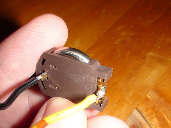
バッテリーホルダーを1個と、あらかじめ剥いておいた銅線を2本用意します。それぞれのワイヤーの一端をバッテリーホルダーの2本のピンにはんだ付けします。接続部分にたっぷりとはんだを塗布して、うまく接続され、適度に耐久性があることを確認してください。
-
ケーブルのはんだ付けが終わったら、この手順の画像のようになるはずです。
-
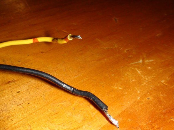
また、ケーブルのもう一方の端も錫メッキしておくとよいでしょう(このステップの3番目の画像のように)。錫メッキが何かわからない場合は、こちらのリンクで詳細をご確認ください: http://www.mediacollege.com/misc/solder/...
-
どのケーブルがバッテリーのプラス端に接続されているのか、またどのケーブルがマイナス端なのかを覚えておくために、各ケーブルにラベルを貼っておくのも良いアイデアです。これは後でとても重要になります。
-
-
-
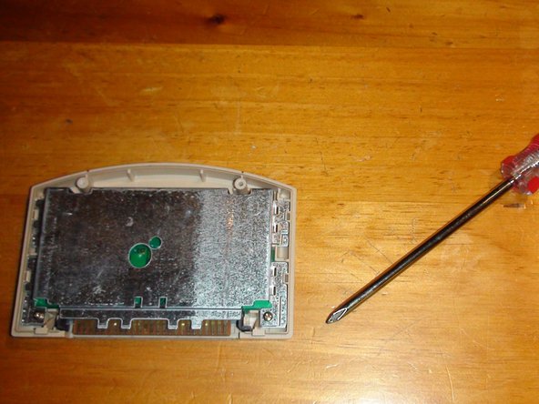
さて、メインイベントです。3.8mmゲームビットをモジュラースクリュードライバーに接続します。ドライバーを使って、カートリッジを固定している2本のゲームビットのネジを外します。ネジを外したら、慎重にカートリッジのバックカバーを外し、内部のメタルシールドを露出させます。
-
次に、プラスヘッドドライバーを手に取り、メタルシールド下側コーナーにある2本のプラスネジを外します。このメタルシールドを外したら、カートリッジの回路基板を露出させます。
-
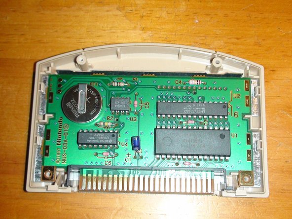
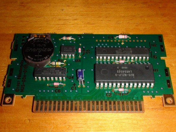
コイン電池が装着されたカートリッジPCBが確認できます。この問題の原因は、これからすぐに解決します。
-
ここから、慎重にPCBをカートリッジの筐体から取り外します。カートリッジピンの黒いプラスチックシールドを外し、PCBを作業スペースに置きます。
-
-
-
-
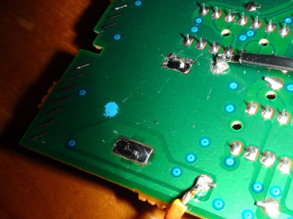
プリント基板を見て、この手順の2番目の画像にマークされている4つのはんだ端子に注目してください。
-
赤で囲んだ2つの端子はバッテリー端子です。これらの端子は、PCBの反対側にあるバッテリーに取り付けられているプラスとマイナスのピンで構成されています。この画像では、プラス端子が基板上の高い位置にあり、マイナス端子が1つ下の位置にあります。
-
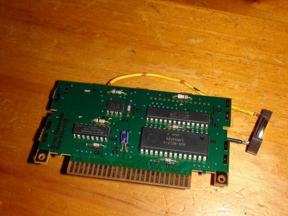
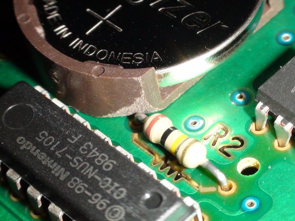
緑色の丸で囲んだ2つの端子は、抵抗の端子です。この2つの端子は、PCBの反対側に見える2つの抵抗の端です。なぜこれらが重要なのでしょうか?パリティバッテリーを接続する端子だからです。
-
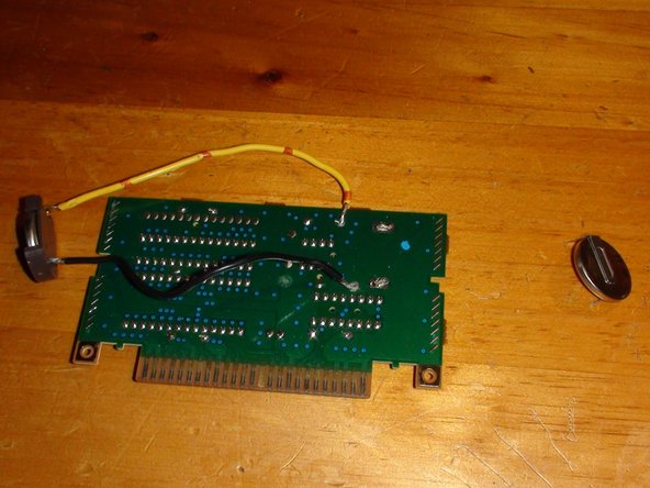
なぜパリティバッテリーを抵抗に接続するのでしょうか?これには理由があります。この手順の最初の画像で、2つのバッテリー端子の周りのPCBに注目してください。回路基板がどのように機能するのかご存じない方は、PCBの薄い緑色の部分(画像で見える)は、ソルダーマスクの下にあるコッパーライニング(裏地)を示しています。
-
このコッパーのライニングは、PCB上の特定の端子間をつなぐものです。この場合、プラス側のバッター端子とその隣の抵抗端子をつなぐ銅線が基板上にあることに気づくでしょう。マイナス端子も同様です。これは2番目の画像に青で記されています。
-
これを確認するには、マルチメーターを使ってバッテリーの2つの端子(赤)の電圧をチェックすることができます。同じように2つの抵抗端子(緑)をチェックすると、バッテリー端子と同じ電圧を表示していることに気づくでしょう。
-
パリティ・バッテリーをこれらの抵抗端子に取り付けることで、電気はPCBを通り続け、カートリッジのSRAMに保存された機密データを保持します。つまり、PCB上のメインバッテリーを交換しても、ボードの電源が切れた瞬間にカートリッジのセーブデータが削除されることはありません。
-
パリティバッテリーのプラス端はPCBのプラス回路に接続する必要があります。パリティは、電池のプラスとマイナスの端がそれぞれの回路に接続されている場合にのみ達成されます。バッテリーを逆に接続すると、バッテリーを直列に接続することになり、電圧が上昇します。
-
-
-
次に、この手順の画像にあるように、パリティ電池をPCBに接続します。ここでは様々なことがうまくいかない可能性があるので、手順2にきちんと従っていること、精密作業用のはんだごての扱いに自信があることを確認してください。
-
パリティ電池ケーブルの両端を、錫メッキが再び溶け始める程度に加熱することから始めます。注意:あまり熱しすぎると、電池本体に悪影響を及ぼすことがあるので注意してください。
-
次に、抵抗器の端子(ステップ5で緑で囲んだ部分)を、はんだが溶け始める程度に加熱します。注意:ここでも端子の熱さに注意してください。抵抗器や基板そのものにダメージを与えたくありません。また、熱すぎるとバッテリーからの電力に余計な抵抗が加わり、SRAMのデータが失われる可能性があります。
-
初心者の方へ: はんだ付けするものの両端を熱する必要があるのは、はんだ自体が液体のように両面に「流れる」必要があり、それは両端が熱いときにのみ可能だからです。今のはんだ端子(手順5の画像)を見ると、これらのはんだがどのように流れるかが、よく見えるかがわかるでしょう。これが目標です。
-
これが最後の確認事項: 基板に接続する際、パリティ・バッテリーのプラスとマイナスを間違えないでください!電池は直列ではなく、パリティにしてください。
-
次に、パリティ・バッテリーのプラス・ケーブルの端を、高抵抗の端子に慎重にはんだ付けします。はんだが抵抗のピンとパリティ・バッテリーのケーブルの端の両方に、液体が適切に流れていることを確認します。この場合も、熱の加え方に注意してください。はんだを溶かす必要がありますが、何も傷つけてはいけません。
-
同じ方法で、パリティ電池のマイナス・ケーブルの端を下側の抵抗端子にはんだ付けします。
-
パリティ電池が端子に正しく取り付けられたと感じたら、はんだを1、2分冷まします。
-
-
この手順は未翻訳です。 翻訳を手伝う。
-
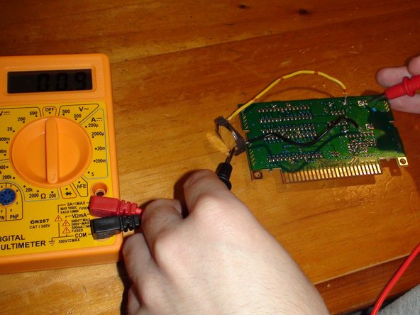
Now to test that you've made a good connection with the solder. Set your Multimeter to 200 Ohms and test the connection between the main battery terminals and the parity battery. For visual reference, do as shown in the two images on this step.
-
The Ohm reading you get by testing the connections should show a solid number somewhere around 1 Ohm. This indicates that you've made a good solder connection.
-
You'll see that the reading I got when testing my negative connection (second image) shows 1.2 Ohms, compared to the much better reading from the positive connection (first image) which shows 0.9. Although it's not perfect, it's all good as long as the number does not variate to far from 1 Ohm. If it does, the connection is loose.
-
Another test to do is to check the voltage now shown when testing the main battery. You should now see the voltage read somewhere higher than 3v rather than when the old battery would show something more along the lines of near 3 or 2.98. Either way, seeing a slightly higher voltage than before means you've successfully created a Parity system.
-
I don't know what would happen if you accidentally put your batteries in Serial, but I'm pretty sure your cartridge would explode (or something like that) if it suddenly had 6 volts running through it. This is why it's important to make sure you put the positive cable of your parity battery onto the positive end of the PCB battery area.
-
-
この手順は未翻訳です。 翻訳を手伝う。
-
IT IS RECOMMENDED TO HAVE ANOTHER PERSON WITH YOU TO HELP WITH THIS STEP
-
Now that the parity battery is attached, it's time to remove the old battery that we'll be replacing.
-
Grab a flat head screwdriver in place it underneath the battery on the other side of the PCB. Now start carefully heating up the solder on one of the main batteries terminals. While melting the solder, use the screwdriver to carefully push the battery out from the board using the screwdriver as a lever.
-
Eventually, the battery should come loose and the pin should fall from the PCB easily, given you're providing enough pushing force with the screwdriver.
-
Follow the same method for removing the other pin from the PCB. This time however, you can pull the battery out while melting the solder rather than using the screwdriver to lever the battery out.
-
Just to be sure, use your Multimeter to test the main battery terminals after you've removed the old battery and check that there's still electricity running through the circuit. If you get a stable voltage reading from the main battery terminals (circled Red in step 5) after you've removed the old battery, then your save game is still safe.
-
-
この手順は未翻訳です。 翻訳を手伝う。
-
Now to clean the old solder out of the main battery terminals. This is done to ensure you can put the new battery in easily.
-
Again, start carefully heating up the solder on and inside the main battery terminals. While the solder's hot and melted, use you Soldering Pump to extract the solder off of the terminal and out of the inside of the terminal. It might also be a good idea to have someone else use the soldering pump for you while you use the soldering iron.
-
If there's still some solder left inside the terminal, you may have to use something thin to file it out. Keep in mind that this is a last resort as there's a risk of tiny bits of solder going everywhere after filing.
-
After cleaning the terminals, the result should be something like the second image of this step.
-
Although it's a bit blurry, you can clearly see that the terminals are very clean and open.
-
-
この手順は未翻訳です。 翻訳を手伝う。
-
Now to connect the new battery onto the PCB. In this guide, I've used a CR2032 Battery Holder designed for use with any and all Nintendo cartridges. However, you're free to use a standard CR2032 battery with pins already attached to it. A battery holder will make future replacements easier.
-
Place the new battery in the same position that the old battery was in on the PCB.
-
NOTE for Battery Holder users: You may need to modify the holder slightly. Take note of the second image in this step. One of my cartridges resistors was placed very close to the battery and resulted in it blocking the placement of the holder. If you're in a similar situation, you will need to file off the corner of your holder as shown.
-
With the battery in place, begin to carefully heat up the terminal and the batteries pins.
-
I use the word "carefully" in the literal sense. Heating up a battery is universally NOT a good idea, but all you need is just enough heat that the replacement solder will flow on to the pin properly.
-
Once the terminals and pins are hot enough, begin applying a generous amount amount of new solder to the space between the pins and the terminals.
-
Once you're done, you should have something that looks like the third image in this step.
-
Let the solder cool off after you're finished. Test the terminals with your Multimeter to make sure everything is still operating normally.
-
-
この手順は未翻訳です。 翻訳を手伝う。
-
Now for the final part. Exercise caution as you did in step 6.
-
Begin heating up one of the terminals your parity battery is attached to. Make sure you're heating up the resistor pin, the terminal, and the parity batteries cable end as you're doing so. While heating up the solder, gently pull on the cable until it comes loose.
-
If you happen to pull off too much solder when detaching the parity batteries cable, quickly start applying more solder to the resistors terminal to ensure the connection remains solid. You don't want to go through all this work for nothing.
-
Do the same thing for the next resistor terminal.
-
After you've taken off the parity battery, get your Multimeter and test both the main battery terminals and the resistor terminals to make sure that your new battery is supplying a solid 3 volts of power to the cartridge.
-
Also check for an Ohm reading between the resistor terminals and the main battery terminals on their respective copper lining circuits. You should again get a reading of around 1 Ohm in your tests.
-
If everything checks out, then that's it! You're done! You've successfully replaced a Nintendo 64 cartridge battery and, if everything went smoothly during the replacement, without losing power to the SRAM chip and deleting your Save Data!
-


カートリッジを分解したときと逆の手順で組み立て直します。すべての作業がうまくいき、すべての手順に正しく従った場合は完了です!おめでとうございます!
カートリッジを分解したときと逆の手順で組み立て直します。すべての作業がうまくいき、すべての手順に正しく従った場合は完了です!おめでとうございます!
4 の人々がこのガイドを完成させました。
以下の翻訳者の皆さんにお礼を申し上げます:
53%

Midori Doiさんは世界中で修理する私たちを助けてくれています! あなたも貢献してみませんか?
翻訳を始める ›

47 件のコメント
Hello Jackson! I think I confused of place when I wrote jejeje
Congratulations on the item! I would like to replace the batteries of my games. What is step 5 ? How do I change the battery without losing memory?
Than you very much.
Regards!!!
Apologies. This guide is unfinished and not meant to be public yet.
Jackson -
The guide is now complete. Good luck!
Jackson -
Right now I’m on mobile, so I’ll come back and point out the specific things I’m referring to. But for now I’ll say, there are major issues with the electrical engineering advice in this guide!
Don’t get me wrong, adding a second battery/power source while replacing the one on the board is correct. However, some of the tests / explanations / information provided in this guide are totally off-base
Tyler Winn - 返信
Please make your follow-up comment soon. I’m eager to know exactly what issues you’ve discovered in this guide.
If something’s wrong, I’m more than happy to rectify it.
Jackson -