メインコンテンツにスキップ

このバージョンは誤った内容を含んでいる可能性があります。最新の承認済みスナップショットに切り替えてください。

必要な工具と部品

  1. この手順は未翻訳です。 翻訳を手伝う。

    : 手順 1、 2の画像 1 : 手順 1、 2の画像 2
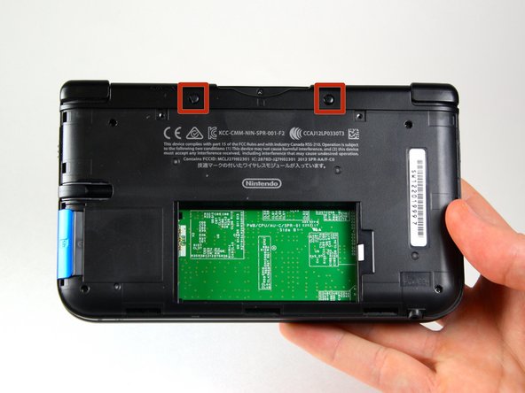
    • Loosen the two #0 Phillips 4.2 mm-length screws located at the top of the back cover.

    • The screws have locking washers that prevent the screws from falling off of the back cover. Leave these locking washers on the screws; it is not necessary to remove the washers for this repair guide.

  2. この手順は未翻訳です。 翻訳を手伝う。

    : 手順 2、 2の画像 1 : 手順 2、 2の画像 2
    • Hold the device so that the cover is facing up.

    • Using a plastic opening tool, pry off the cover starting at the top right corner.

    • Hold the edge of the cover to ensure it does not reattach.

    • Look for the small section below the stylus compartment. Pry off the cover at that point if it is still attached.

    • Take off the cover of the device and set it aside.

  3. この手順は未翻訳です。 翻訳を手伝う。

    : 手順 3、 3の画像 1 : 手順 3、 3の画像 2 : 手順 3、 3の画像 3
    • Insert the plastic opening tool into the opening located on the right side of the battery.

    • Pry off the battery from the lower casing.

    • Lift the battery out of the case and set aside.

  4. この手順は未翻訳です。 翻訳を手伝う。

    : 手順 4、 2の画像 1 : 手順 4、 2の画像 2
    この手順で使用する道具:
    Tweezers
    $4.99
    購入する
    • Using tweezers pull out the rubber bumpers that are located at the top of the device on either side of the game cartridge compartment.

  5. : 手順 5、 2の画像 1 : 手順 5、 2の画像 2
    • #00プラスドライバーを使って、6.2mmネジを6本外します。

  6. : 手順 6、 1の画像 1
    • #00プラスドライバーを使って、ゲームカートリッジスロットの上に留められた2.3mmネジを外します。

  7. この手順は未翻訳です。 翻訳を手伝う。

    : 手順 7、 3の画像 1 : 手順 7、 3の画像 2 : 手順 7、 3の画像 3
    • Make sure the SD card has been removed. With a plastic opening tool pry off the lower case starting at the bottom edge and working around the perimeter.

    • Two ribbon cables connect the case to the circuit board. Be careful to not pull the case too hard and rip the ribbon cables.

  8. この手順は未翻訳です。 翻訳を手伝う。

    : 手順 8、 3の画像 1 : 手順 8、 3の画像 2 : 手順 8、 3の画像 3
    • Remove the ribbon cables located underneath the left and right bumpers by prying up the base of the cables with a plastic opening tool.

    • Completely remove the lower case from the rest of the device and set aside.

  9. この手順は未翻訳です。 翻訳を手伝う。

    : 手順 9、 2の画像 1 : 手順 9、 2の画像 2
    • Position the device such that the game cartridge slot is located at the top.

    • Locate the circle pad on the right side of the device.

    • Remove the two 7.5 mm screws on the upper left and the bottom right corners.

  10. この手順は未翻訳です。 翻訳を手伝う。

    : 手順 10、 2の画像 1 : 手順 10、 2の画像 2
    • Using a plastic opening tool pop off the circle pad joystick.

    • Do not use excessive force with the plastic opening tool. There is a ribbon attaching the circle pad joystick to the motherboard that will remain attached.

    • There is a loose washer located in between the circle pad joystick and the circle pad. Use caution and do not lose this piece.

  11. この手順は未翻訳です。 翻訳を手伝う。

    : 手順 11、 2の画像 1 : 手順 11、 2の画像 2
    • Using the flat head side of the spudger carefully lift up the retaining flap that attaches the circle pad ribbon to the motherboard.

    • Remove the ribbon and circle pad joystick.

  12. この手順は未翻訳です。 翻訳を手伝う。

    : 手順 12、 2の画像 1 : 手順 12、 2の画像 2
    • Position the device such that the game cartridge slot is located at the top.

    • Locate the IR board located on the upper right side of the motherboard.

    • The IR board is installed upside-down in these photos by mistake. Installing it this way will result in your DS failing to start. Note the orientation of your IR board before you remove it, and reinstall it the same way.

    • Remove the IR board with a plastic opening tool by inserting the tool below the IR board and gently prying up.

  13. この手順は未翻訳です。 翻訳を手伝う。

    : 手順 13、 2の画像 1 : 手順 13、 2の画像 2
    • Using a plastic opening tool, pry off the Wi-Fi board.

    • The Wi-Fi board will still be connected by a wire and it is not necessary to completely remove it for this step. Simply place it out of the way for this step.

  14. この手順は未翻訳です。 翻訳を手伝う。

    : 手順 14、 2の画像 1 : 手順 14、 2の画像 2
    この手順で使用する道具:
    Tweezers
    $4.99
    購入する
    • Locate the volume switch on the right side of the motherboard next to the circle pad joystick.

    • Using tweezers, carefully remove the volume board from the casing. It will still be attached to the motherboard by a ribbon cable.

  15. この手順は未翻訳です。 翻訳を手伝う。

    : 手順 15、 1の画像 1
    • Using the flat head side of the spudger carefully lift up the flap that attaches the volume board ribbon to the motherboard.

    • Remove the volume board and set aside.

  16. この手順は未翻訳です。 翻訳を手伝う。

    : 手順 16、 2の画像 1 : 手順 16、 2の画像 2
    • Remove the black plastic pieces from the lower left and right hand corners with either your fingers or tweezers.

    • You can also remove these pieces easily by carefully lifting up the 3DS and holding it upside-down. They normally fall right out, but don't lose them!

  17. この手順は未翻訳です。 翻訳を手伝う。

    : 手順 17、 3の画像 1 : 手順 17、 3の画像 2 : 手順 17、 3の画像 3
    • Using the flat head side of the spudger carefully lift up the flap that attaches the two smaller ribbons to the motherboard.

    • These flaps are located on the top right and bottom right side of the motherboard.

    • Remove the ribbons from the flap.

  18. この手順は未翻訳です。 翻訳を手伝う。

    : 手順 18、 3の画像 1 : 手順 18、 3の画像 2 : 手順 18、 3の画像 3
    • Using the flat head side of the spudger carefully lift up the flaps that attach the wider ribbons to the motherboard.

    • For the wider ribbons make sure to lift the flaps from the white side.

    • Remove the ribbons from the opened flaps.

  19. この手順は未翻訳です。 翻訳を手伝う。

    : 手順 19、 2の画像 1 : 手順 19、 2の画像 2
    • Using the flat head side of the spudger carefully lift up the flap that attaches the ribbon to the motherboard.

    • For this flap lift from the black side.

    • Remove the ribbon from the flap.

    • Reassembly: This wide ribbon is the one with the BLACK STRIPE and goes on the upper (visible) side of the motherboard during reassembly.

  20. この手順は未翻訳です。 翻訳を手伝う。

    : 手順 20、 2の画像 1 : 手順 20、 2の画像 2
    • Remove ten 3.0 mm screws that are located around the face of the motherboard.

  21. この手順は未翻訳です。 翻訳を手伝う。

    : 手順 21、 2の画像 1 : 手順 21、 2の画像 2
    • The motherboard will still be attached at the top right hand corner so do not completely detach it at this point.

    • Carefully lift the board straight up just enough to clear the two plastic mounts located near the top corners of the cartridge slot.

    • Gently flip the motherboard over the top side.

  22. この手順は未翻訳です。 翻訳を手伝う。

    : 手順 22、 2の画像 1 : 手順 22、 2の画像 2
    • Using the flat head side of the spudger carefully lift up the flap that attaches the wider ribbon on the upper right side to the motherboard.

    • Make sure to lift the flap from the white side.

    • Remove the ribbon from the opened flap.

    • Set the motherboard aside.

ゴール

47 の人々がこのガイドを完成させました。

作成者

9人の作成者と共同で作成されました。

Charlene Donlon

メンバー登録日: 04/08/14

10,243 ポイント

8のガイドは作成済み

チーム

Cal Poly, Team 9-13, Regan Spring 2014 Cal Poly, Team 9-13, Regan Spring 2014人のメンバー

CPSU-REGAN-S14S9G13

5 メンバー

44のガイドは作成済み

13 件のコメント

yes but what about putting it back in?

jefbt - 返信

Does anyone know how to fix the flap on the ribbon because I accidentally removed the whole thing

Carlos Mendez - 返信

How do you fix it so it will stop shutting down on start up?

shawn66674 - 返信

my 3DS XL in turn on, speaker making cracking sound, no display, then power off. is this motherboard issue.

neofighter103 - 返信

I have the same problem, did you were able to fix it ?

soyeliel -

コメントを追加

統計データ:

過去 24時間: 34

過去 7 日: 223

過去 30 日: 914

今までの合計 70,448