メインコンテンツにスキップ

Ninja NJ600 Power Cord Replacement

必要な工具と部品

  1. Ninja NJ600 Power Cord Replacement, Blender Base Cover: 手順 1、 2の画像 1 Ninja NJ600 Power Cord Replacement, Blender Base Cover: 手順 1、 2の画像 2
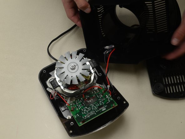
    • Remove the five screws (13mm long, 6mm head diameter) using a Phillips #2 screwdriver.

  2. Ninja NJ600 Power Cord Replacement: 手順 2、 2の画像 1 Ninja NJ600 Power Cord Replacement: 手順 2、 2の画像 2
    • Without removing any screws, you can pull the 2nd layer free from the base. Do this now and set it down gently next to the base.

    • The power cord runs through a hole in the side of this layer. Squeeze the cord and pull it through the hole to separate the layer from the cord.

  3. Ninja NJ600 Power Cord Replacement: 手順 3、 3の画像 1 Ninja NJ600 Power Cord Replacement: 手順 3、 3の画像 2 Ninja NJ600 Power Cord Replacement: 手順 3、 3の画像 3
    • Using the Phillips #2 screwdriver, remove these six screws (13mm long, 6mm head diameter). Then carefully remove this layer, and rest it next to the blender base.

    • Be careful not to damage the two wires that are keeping this third layer attached to the base.

  4. Ninja NJ600 Power Cord Replacement, Power Cord: 手順 4、 1の画像 1
    • Remove these two screws (10mm long, 5mm head diameter) using a Phillips #2 screwdriver.

  5. Ninja NJ600 Power Cord Replacement: 手順 5、 1の画像 1
    • Your blender and power cord should look like this now that the two screws have been removed.

    • In the next steps we will highlight two issues that your power cord may have.

  6. Ninja NJ600 Power Cord Replacement: 手順 6、 1の画像 1
    • Your power cord is soldered to the circuit board as shown.

    • A loose or damaged connection could explain why your blender is not turning on.

    • Desolder the connection using the iFixit guide that describes this process.

    • Solder the wires back on to the circuit board. Refer to the iFixit soldering guide for assistance.

    • Soldering iron is very hot, use caution when handling

  7. Ninja NJ600 Power Cord Replacement: 手順 7、 2の画像 1 Ninja NJ600 Power Cord Replacement: 手順 7、 2の画像 2
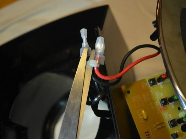
    • If there were no issues with the soldering connection in Step 6, check the wiring in the picture shown.

    • Remove the zip ties with a pair of scissors. Then remove the plastic that covers the wires.

    • If the wires underneath the plastic covers are loose or disconnected, try to desolder and solder the wires. Use the iFixit soldering guide to assist in this step.

    • Soldering iron is very hot, use caution when handling

終わりに

To reassemble your device, follow these instructions in reverse order.

作成者

4人の作成者と共同で作成されました。

Trevor Waite

メンバー登録日: 04/01/15

275 ポイント

1ガイドが承認済み

チーム

Cal Poly, Team 24-2, Lancaster Spring 2015 Cal Poly, Team 24-2, Lancaster Spring 2015人のメンバー

CPSU-LANCASTER-S15S24G2

4 メンバー

6のガイドは作成済み

0 件のコメント

コメントを追加

統計データ:

過去 24時間: 0

過去 7 日: 2

過去 30 日: 11

今までの合計 2,942