このバージョンは誤った内容を含んでいる可能性があります。最新の承認済みスナップショットに切り替えてください。
必要な工具と部品
-
この手順は未翻訳です。 翻訳を手伝う。
-
Then next step is removing the seven Philips #00 screws that hold the rear face plate on.
-
There are screws hidden in three separate spots.
-
One is under the rubber doors on the left side of the camera. the next one at the eye hole.
-
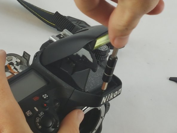
The final one involves taking off the small dial that is about half an inch to the right of the eye hole.
-
Removing this dial involves putting a spungder tool behind it and applying a gradual amount of pressure.
-
-
-
この手順は未翻訳です。 翻訳を手伝う。
-
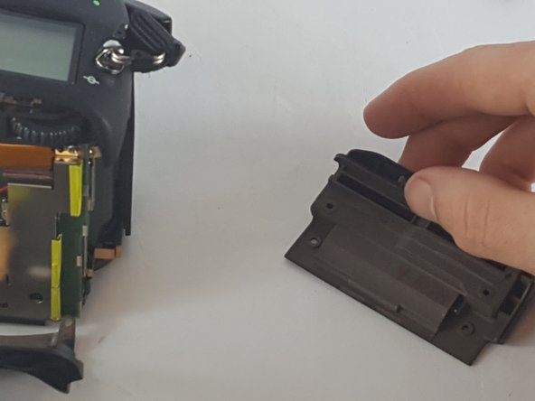
It is now possible to remove the last three Philips #00 screws that are hidden under the memory card slot door.
-
The screws come out and the cover comes straight off.
-
The last cover plate is the top. The top is held on by two screws located just beneath the rim of the cover.
-
-
この手順は未翻訳です。 翻訳を手伝う。
-
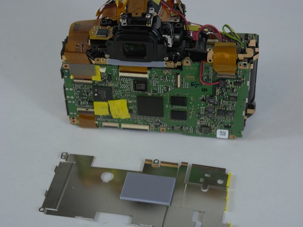
The rear side of the camera is where the motherboard is located. It is visible after you have taken off the rear face plate.
-
Remove the shield that protects it from static first.
-
This shield has six Philips #00 screws that are positioned around the edge of the shield.
-
After removal of the screws the shield will come free from the motherboard.
-
-
この手順は未翻訳です。 翻訳を手伝う。
-
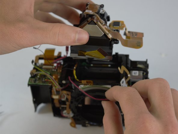
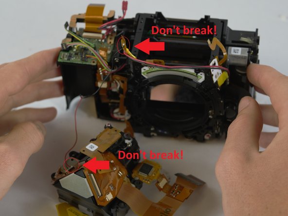
This is where having the motherboard off is necessary as the screws we need are burrowed at the very heart of the camera.
-
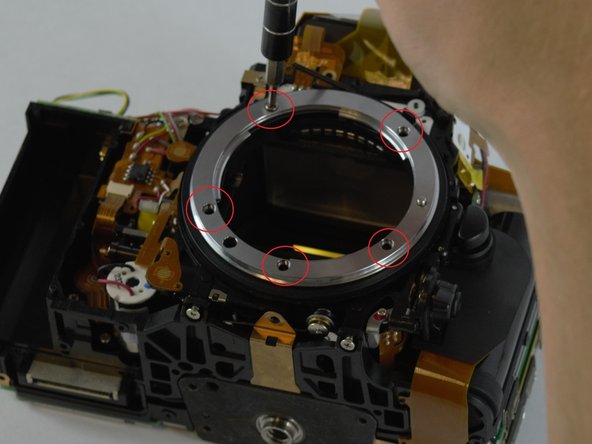
Four more screws and two ribbon cables marked by the red circles need to be removed to release what we need.
-
The blue circles indicate the screws that don't need to be undone to get to what we need.
-


4 の人々がこのガイドを完成させました。
チーム

USF Tampa, Team 4-4, Lacy Spring 2016 USF Tampa, Team 4-4, Lacy Spring 2016人のメンバー
USFT-LACY-S16S4G4
3 メンバー
6のガイドは作成済み
コメント 1 件
I had a D610 where the mirror wouldn't go down properly after is was knocked, I had a look at fixing it but it is basically unserviceable apart from the most basic and superficial repairs repairs, shame really, it was a nice old camera, but to be honest I wasn't surprised. I'm going to buy another second hand and keep the bits for spares or as a memento mori.