メインコンテンツにスキップ

Nikon D3000 Motherboard Replacement

必要な工具と部品

  1. Nikon D3000 Motherboard Replacement, Motherboard: 手順 1、 2の画像 1 Nikon D3000 Motherboard Replacement, Motherboard: 手順 1、 2の画像 2
    • Remove six 3 mm x 2.5 mm Phillips head screws from the bottom right of the camera bottom.

    • Remove three 3 mm x 5.5 mm Phillips head screws from the bottom left of the camera bottom

    • Lift the battery cover and remove two 3 mm x 5 mm Phillips head screws.

  2. Nikon D3000 Motherboard Replacement: 手順 2、 3の画像 1 Nikon D3000 Motherboard Replacement: 手順 2、 3の画像 2 Nikon D3000 Motherboard Replacement: 手順 2、 3の画像 3
    • Remove the two 3 mm x 5.5 mm Phillips head screws from the either side of the viewfinder.

    • Remove four 3 mm x 5.5 mm Phillips head screws from the sides of the camera.

    • Remove two 3 mm x 4 mm Phillips head screws from under the SD card door.

  3. Nikon D3000 Motherboard Replacement: 手順 3、 2の画像 1 Nikon D3000 Motherboard Replacement: 手順 3、 2の画像 2
    • Use the following process for removing all ribbon connectors.

    • Lift the back of the camera and, using the blue prying tool, lift the tab from the LCD ribbon connector.

    • Slide the ribbon connector away from the bottom of the camera and remove the back cover containing the LCD to expose the motherboard.

  4. Nikon D3000 Motherboard Replacement: 手順 4、 2の画像 1 Nikon D3000 Motherboard Replacement: 手順 4、 2の画像 2
    • Soldering irons are hot; take all necessary precautions to not burn yourself or equipment.

    • Be sure to label each gray wire to be removed from the motherboard as they are the same color and can be mixed up during reassembly.

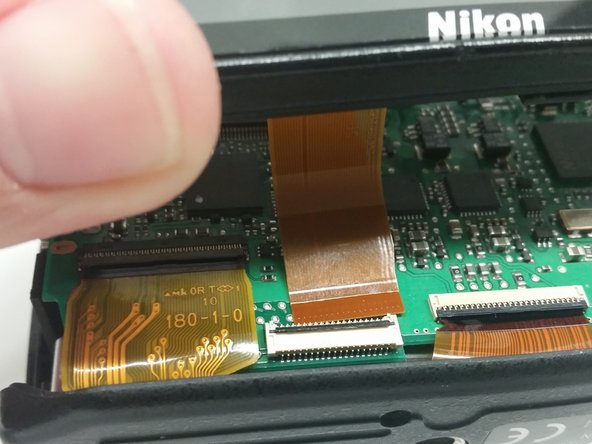
    • Lift the tab on the ribbon connector and pull away the ribbon to expose a 4 mm x 4 mm Phillips head screw.

    • De-solder the red (upper), two grey (lower), red (lower), and blue (lower) wires from the motherboard.

    • Remove five 4 mm x 4 mm Phillips head screws holding the motherboard to the camera frame.

  5. Nikon D3000 Motherboard Replacement: 手順 5、 2の画像 1 Nikon D3000 Motherboard Replacement: 手順 5、 2の画像 2
    • Lift the tabs and pull away the ribbon connectors shown .

    • Lift the motherboard and disconnect the grey connector from the bottom.

    • Disconnect and remove the motherboard.

終わりに

To reassemble your device, follow these instructions in reverse order.

3 の人々がこのガイドを完成させました。

作成者

1人の作成者と共同作成されました。

Randall Heath

メンバー登録日: 08/25/15

851 ポイント

3のガイドは作成済み

チーム

USF Tampa, Team 14-7, Meier Fall 2015 USF Tampa, Team 14-7, Meier Fall 2015人のメンバー

USFT-MEIER-F15S14G7

4 メンバー

6のガイドは作成済み

0 件のコメント

コメントを追加

統計データ:

過去 24時間: 0

過去 7 日: 1

過去 30 日: 13

今までの合計 3,891