メインコンテンツにスキップ

このバージョンは誤った内容を含んでいる可能性があります。最新の承認済みスナップショットに切り替えてください。

必要な工具と部品

  1. この手順は未翻訳です。 翻訳を手伝う。

    : 手順 1、 1の画像 1
    • Remove the memory stick from the camera.

    • Remove the batteries from the camera.

  2. この手順は未翻訳です。 翻訳を手伝う。

    : 手順 2、 2の画像 1 : 手順 2、 2の画像 2
    • Remove all six 4.3mm silver screws along the perimeter of the camera using the Phillips #00 screwdriver.

    • There is one screw hidden under the AV cover that also needs to be removed.

  3. この手順は未翻訳です。 翻訳を手伝う。

    : 手順 3、 1の画像 1
    • Pry the back cover from the left side of the camera. Remove the cover gently.

  4. この手順は未翻訳です。 翻訳を手伝う。

    : 手順 4、 1の画像 1
    • Pry back the front cover of the camera starting from the right side.

  5. この手順は未翻訳です。 翻訳を手伝う。

    : 手順 5、 1の画像 1
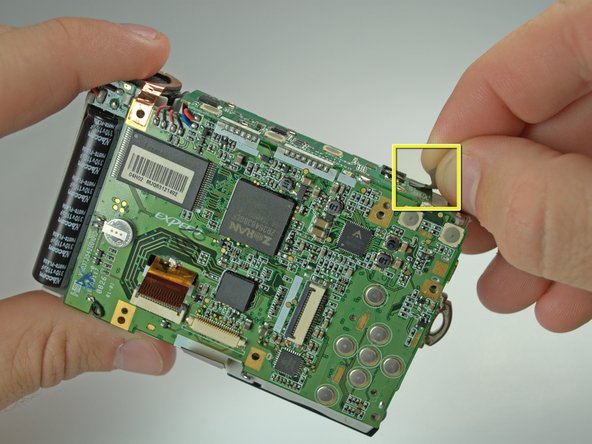
    • This is where energy for the flash is stored. Even with batteries removed, if you touch these connections, you can be shocked, depending on if the flash capacitor has a stored charge. It may not have a stored charge, but work around this assuming it does.

    • Newer cameras of decent quality usually have a bleeder resistor to drain the flash capacitor. This may not work anymore and the flash capacitor may still have a charge.

  6. この手順は未翻訳です。 翻訳を手伝う。

    : 手順 6、 1の画像 1
    • Remove the tape on the right side of the LCD screen.

    • Gently lift the LCD screen from its base.

    • Don't tug on the screen because it is still connected to the motherboard.

  7. この手順は未翻訳です。 翻訳を手伝う。

    : 手順 7、 1の画像 1
    • Lift the black latch connecting the LCD ribbon to the motherboard.

    • Gently pull the LCD ribbon out.

  8. この手順は未翻訳です。 翻訳を手伝う。

    : 手順 8、 2の画像 1 : 手順 8、 2の画像 2
    • Remove the 6 Phillips #00 screws anchoring the LCD base to the motherboard.

    • Remove the LCD base plate.

  9. この手順は未翻訳です。 翻訳を手伝う。

    : 手順 9、 1の画像 1
    • Lift the black latch connecting the LCD ribbon to the motherboard.

    • Gently pull the lens ribbon out.

  10. この手順は未翻訳です。 翻訳を手伝う。

    : 手順 10、 1の画像 1
    • Desolder the connection of the motherboard to the lens ribbon using a soldering iron and desoldering wick.

  11. この手順は未翻訳です。 翻訳を手伝う。

    : 手順 11、 1の画像 1
    • Lift up the black and copper covering on the left side of the camera.

  12. この手順は未翻訳です。 翻訳を手伝う。

    : 手順 12、 1の画像 1
    • Pull the wiring at the top right of the camera away from the lens with tweezers.

  13. この手順は未翻訳です。 翻訳を手伝う。

    : 手順 13、 1の画像 1
    • Remove the cross-hair shaped wire cap to the left of the lens.

  14. この手順は未翻訳です。 翻訳を手伝う。

    : 手順 14、 2の画像 1 : 手順 14、 2の画像 2
    • Remove the 3 screws holding the lens to the camera frame.

    • Two 3.8mm black Phillips #00 screws on the sides of the lens.

    • One 4.6mm silver Phillips #00 screw on the bottom of the lens.

  15. この手順は未翻訳です。 翻訳を手伝う。

    : 手順 15、 1の画像 1
    • There is a screw behind flash tube holding lens. Remove it, then gently pull the lens out. Be sure that the lens's ribbon clears the motherboard.

  16. この手順は未翻訳です。 翻訳を手伝う。

    : 手順 16、 2の画像 1 : 手順 16、 2の画像 2
    • Remove the tape on the top of the logic board.

  17. この手順は未翻訳です。 翻訳を手伝う。

    : 手順 17、 1の画像 1
    • Remove the 4 Phillips #00 screws holding the top of the logic board onto the camera frame.

  18. この手順は未翻訳です。 翻訳を手伝う。

    : 手順 18、 1の画像 1
    • Desolder the joint of the top and back of the logic board using a soldering iron and desoldering wick.

    • You will need to have soldering equipment to complete this step.

  19. この手順は未翻訳です。 翻訳を手伝う。

    : 手順 19、 1の画像 1
    • Move the top of the logic board to the side, exposing the top of the frame.

    • Desolder the two connections on the top right of the logic board using a soldering iron and desolering wick.

    • You will need to have soldering equipment to complete this step.

ゴール

3 の人々がこのガイドを完成させました。

作成者

5人の作成者と共同で作成されました。

Aaron

メンバー登録日: 10/06/10

278 ポイント

1ガイドが承認済み

チーム

Cal Poly, Team 9-23, Regan Fall 2010 Cal Poly, Team 9-23, Regan Fall 2010人のメンバー

CPSU-REGAN-F10S9G23

4 メンバー

10のガイドは作成済み

0 件のコメント

コメントを追加

統計データ:

過去 24時間: 0

過去 7 日: 7

過去 30 日: 11

今までの合計 3,556