メインコンテンツにスキップ

NEC LCD1770NX Capacitor Replacement

必要な工具と部品

  1. NEC LCD1770NX Capacitor Replacement, Stand: 手順 1、 2の画像 1 NEC LCD1770NX Capacitor Replacement, Stand: 手順 1、 2の画像 2
    • Place the monitor face down on a clean, flat surface.

  2. NEC LCD1770NX Capacitor Replacement: 手順 2、 2の画像 1 NEC LCD1770NX Capacitor Replacement: 手順 2、 2の画像 2
    • Firmly remove the back panel of the stand by pulling it up and away from the monitor.

  3. NEC LCD1770NX Capacitor Replacement: 手順 3、 2の画像 1 NEC LCD1770NX Capacitor Replacement: 手順 3、 2の画像 2
    • Unscrew the two 6mm Phillips PH2 screws to detach the stand enclosure from the stand.

  4. NEC LCD1770NX Capacitor Replacement: 手順 4、 2の画像 1 NEC LCD1770NX Capacitor Replacement: 手順 4、 2の画像 2
    • Firmly grasp the stand enclosure with your hand and slide it to base of stand.

  5. NEC LCD1770NX Capacitor Replacement: 手順 5、 1の画像 1
    • Unscrew the two 14.5mm Phillips PH2 screws holding the stand to the monitor.

  6. NEC LCD1770NX Capacitor Replacement: 手順 6、 2の画像 1 NEC LCD1770NX Capacitor Replacement: 手順 6、 2の画像 2
    • Lift the the stand straight up to remove it.

  7. NEC LCD1770NX Capacitor Replacement, Monitor Enclosure: 手順 7、 3の画像 1 NEC LCD1770NX Capacitor Replacement, Monitor Enclosure: 手順 7、 3の画像 2 NEC LCD1770NX Capacitor Replacement, Monitor Enclosure: 手順 7、 3の画像 3
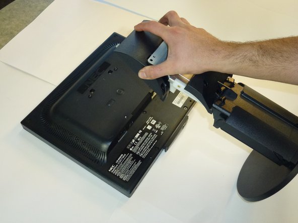
    • Place the monitor screen face up.

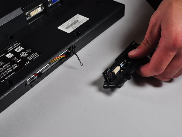
    • Pull the frame off by placing your fingers on the inside of the frame and pulling out and up, the frame should snap off.

    • Continue your way around the screen.

  8. NEC LCD1770NX Capacitor Replacement: 手順 8、 3の画像 1 NEC LCD1770NX Capacitor Replacement: 手順 8、 3の画像 2 NEC LCD1770NX Capacitor Replacement: 手順 8、 3の画像 3
    • Unscrew the two 7mm screws from the bottom of the button assembly.

    • Do not pull the button assembly out too quickly or with too much force! Damage to the wires can occur.

    • Pull the button assembly out a few inches and unplug the colored cables.

  9. NEC LCD1770NX Capacitor Replacement: 手順 9、 2の画像 1 NEC LCD1770NX Capacitor Replacement: 手順 9、 2の画像 2
    • Unscrew the gold colored 7mm Phillips PH000 screw holding the button assembly to the monitor.

    • Remove the button assembly from the monitor.

  10. NEC LCD1770NX Capacitor Replacement: 手順 10、 1の画像 1
    • With the monitor face-down, unscrew the 5 7mm Phillips PH2 screws around the outside of the enclosure.

  11. NEC LCD1770NX Capacitor Replacement: 手順 11、 3の画像 1 NEC LCD1770NX Capacitor Replacement: 手順 11、 3の画像 2 NEC LCD1770NX Capacitor Replacement: 手順 11、 3の画像 3
    • Unscrew the 2 14.5mm Phillips PH2 screws located on the raised center of the enclosure.

    • Carefully pull the enclosure off the monitor.

  12. NEC LCD1770NX Capacitor Replacement: 手順 12、 2の画像 1 NEC LCD1770NX Capacitor Replacement: 手順 12、 2の画像 2
    • Unscrew the 10 5mm Philips PH2 screws holding the metal casing to the monitor.

  13. NEC LCD1770NX Capacitor Replacement: 手順 13、 2の画像 1 NEC LCD1770NX Capacitor Replacement: 手順 13、 2の画像 2
    • Pull the the metal casing off of the monitor to reveal the motherboards.

  14. NEC LCD1770NX Capacitor Replacement, Power Circuit Board: 手順 14、 3の画像 1 NEC LCD1770NX Capacitor Replacement, Power Circuit Board: 手順 14、 3の画像 2 NEC LCD1770NX Capacitor Replacement, Power Circuit Board: 手順 14、 3の画像 3
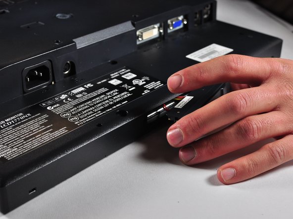
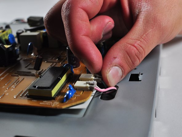
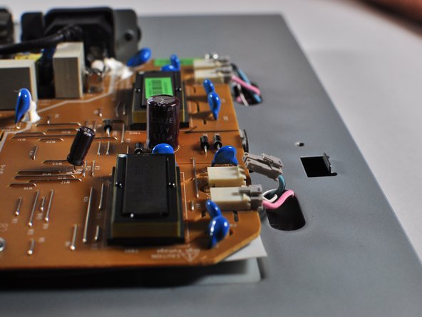
    • Make a note or use a pen to mark which plugs correspond to which colors. (Pink or Blue)

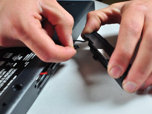
    • Remove the four plugs on the brown circuit board by pulling up on the tabs and wiggling them out. You could also use a spudger to help you lift little clips holding them in.

  15. NEC LCD1770NX Capacitor Replacement: 手順 15、 3の画像 1 NEC LCD1770NX Capacitor Replacement: 手順 15、 3の画像 2 NEC LCD1770NX Capacitor Replacement: 手順 15、 3の画像 3
    この手順で使用する道具:
    Large Needle Nose Pliers
    $4.99
    購入する
    • Locate the several multi-wire connectors on the board.

    • These connect several parts of each board together and consist of several different colors of wires. There is also a zip-tie holding the two sets of wires together that you can cut if it is getting in your way.

    • Disconnect the three plastic connectors from the blue colored boards by pulling them up while wiggling them.

    • Some force is necessary, it may also help to use the Large Needle Nose Pliers.

  16. NEC LCD1770NX Capacitor Replacement: 手順 16、 1の画像 1
    この手順で使用する道具:
    Phillips #1 Screwdriver
    $5.49
    購入する
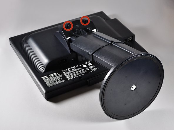
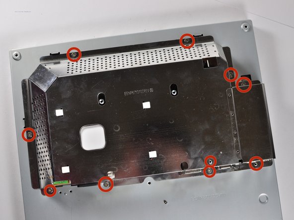
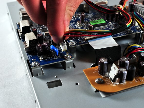
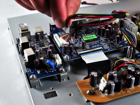
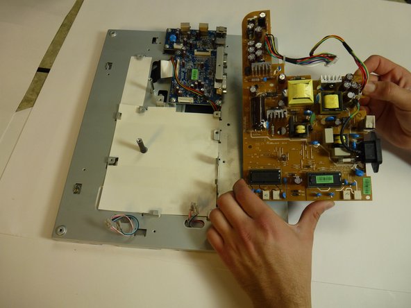
    • Locate the large black power plug.

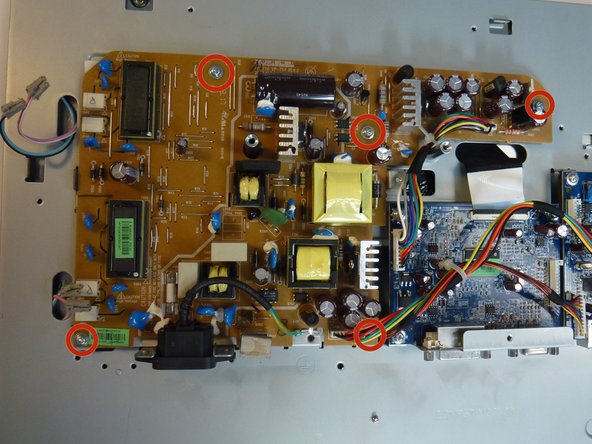
    • Using a Phillips #1 Screwdriver, unscrew the two 8mm colts holding the black tabs to the metal frame.

  17. NEC LCD1770NX Capacitor Replacement: 手順 17、 1の画像 1
    • Locate and remove the gold colored 10mm Philips screw located near the black power plug. It holds in a wire that connects to the power plug.

  18. NEC LCD1770NX Capacitor Replacement: 手順 18、 2の画像 1 NEC LCD1770NX Capacitor Replacement: 手順 18、 2の画像 2
    • Remove 5 8mm Phillip1 screws, with a Philips 1 screwdriver, located in various places on the board.

  19. NEC LCD1770NX Capacitor Replacement: 手順 19、 2の画像 1 NEC LCD1770NX Capacitor Replacement: 手順 19、 2の画像 2
    • Lift the brown power supply board off of the frame and set it aside.

  20. NEC LCD1770NX Capacitor Replacement, Capacitor: 手順 20、 1の画像 1
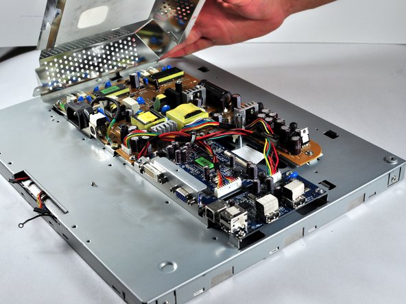
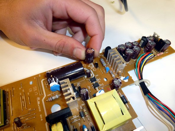
    • Find the faulty capacitor on the board.

    • Bad capacitors can be identified by swelling or bursting at the top.

  21. NEC LCD1770NX Capacitor Replacement: 手順 21、 1の画像 1
    • Flip the board over and find the corresponding solder joints. Capacitors have two joints on the opposite side of the circuit board.

    • Make sure you identify the correct solder joints! We wouldn't want you to desolder the wrong component!

    • Remember which direction the white stripe on the capacitor is facing! Orientation is important for a capacitor! The markings on the board should also remind which way to face the capacitor.

  22. NEC LCD1770NX Capacitor Replacement: 手順 22、 2の画像 1 NEC LCD1770NX Capacitor Replacement: 手順 22、 2の画像 2
    • Use a Soldering Station and Desoldering Braid to remove the solder from the two joints.

  23. NEC LCD1770NX Capacitor Replacement: 手順 23、 2の画像 1 NEC LCD1770NX Capacitor Replacement: 手順 23、 2の画像 2
    • Remove the capacitor from the board, you may need to straighten out the leads before you can take it out easily.

終わりに

To reassemble your device, follow these instructions in reverse order.

作成者

3人の作成者と共同で作成されました。

Charlie Mohr

メンバー登録日: 10/21/13

353 ポイント

3のガイドは作成済み

チーム

Cal Poly, Team 11-36, Amido Fall 2013 Cal Poly, Team 11-36, Amido Fall 2013人のメンバー

CPSU-AMIDO-F13S11G36

5 メンバー

7のガイドは作成済み

コメント 1 件

Hi, the content was comprehensive. Please comment on the electrolytic capacitor . Thank you.

fc fcbuy - 返信

コメントを追加

統計データ:

過去 24時間: 0

過去 7 日: 1

過去 30 日: 3

今までの合計 1,040