メインコンテンツにスキップ

Motorola V60s Logic Board Replacement

必要な工具と部品

  1. Motorola V60s Logic Board Replacement, Battery: 手順 1、 3の画像 1 Motorola V60s Logic Board Replacement, Battery: 手順 1、 3の画像 2 Motorola V60s Logic Board Replacement, Battery: 手順 1、 3の画像 3
    • Push in release lever towards top of phone, then use blue spudger to pry case off.

    • After case is removed from the back of the phone, you can simply use your hands to take it the rest of the way off.

    • Set cover aside in a safe location.

  2. Motorola V60s Logic Board Replacement: 手順 2、 2の画像 1 Motorola V60s Logic Board Replacement: 手順 2、 2の画像 2
    • Carefully grab battery towards bottom of phone.

    • Lift from bottom and take out of phone, set aside in a safe location.

  3. Motorola V60s Logic Board Replacement, Logic Board: 手順 3、 2の画像 1 Motorola V60s Logic Board Replacement, Logic Board: 手順 3、 2の画像 2
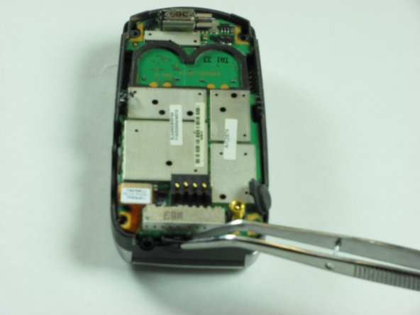
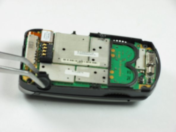
    • Unscrew four corner screws with T6 screwdriver.

    • Note: The two top screws are short and silver. The two bottom screws are black and long.

  4. Motorola V60s Logic Board Replacement: 手順 4、 3の画像 1 Motorola V60s Logic Board Replacement: 手順 4、 3の画像 2 Motorola V60s Logic Board Replacement: 手順 4、 3の画像 3
    • Use a spudger to gently pry off back chassis. Wedge the spudger in crevice between back panel and phone and lift.

  5. Motorola V60s Logic Board Replacement: 手順 5、 3の画像 1 Motorola V60s Logic Board Replacement: 手順 5、 3の画像 2 Motorola V60s Logic Board Replacement: 手順 5、 3の画像 3
    • Starting from left side of phone, remove side buttons and place aside.

    • Note: There should be three buttons. One on each side, and the top.

    • Return phone to starting orientation when done.

  6. Motorola V60s Logic Board Replacement: 手順 6、 3の画像 1 Motorola V60s Logic Board Replacement: 手順 6、 3の画像 2 Motorola V60s Logic Board Replacement: 手順 6、 3の画像 3
    • Gently remove orange ribbon cable by prying up with spudger.

  7. Motorola V60s Logic Board Replacement: 手順 7、 2の画像 1 Motorola V60s Logic Board Replacement: 手順 7、 2の画像 2
    • Use a spudger to pry up logic board by wedging in between logic board and chassis and lifting.

    • Note: Orange ribbon cable is fragile and can be broken.

終わりに

To reassemble your device, follow these instructions in reverse order.

ある他の人がこのガイドを完成しました。

作成者

5人の作成者と共同で作成されました。

Eric Freeman

メンバー登録日: 01/26/10

10 ポイント

7のガイドは作成済み

チーム

Cal Poly, Team 8-48, Regan Winter 2010 Cal Poly, Team 8-48, Regan Winter 2010人のメンバー

CPSU-REGAN-W10S8G48

4 メンバー

13のガイドは作成済み

0 件のコメント

コメントを追加

統計データ:

過去 24時間: 0

過去 7 日: 0

過去 30 日: 1

今までの合計 1,865