メインコンテンツにスキップ

このバージョンは誤った内容を含んでいる可能性があります。最新の承認済みスナップショットに切り替えてください。

必要な工具と部品

  1. この手順は未翻訳です。 翻訳を手伝う。

    : 手順 1、 1の画像 1
    • Remove the back battery cover by pressing the tab to the left, and lifting.

    • A small screwdriver can aid this process.

  2. この手順は未翻訳です。 翻訳を手伝う。

    : 手順 2、 1の画像 1
    • Remove the batteries currently in the radio.

    • When you're ready to add new batteries, place Ni-MH or AAA replacement batteries in the specified slots.

    • The orientation of the batteries is specified in the battery compartment.

  3. この手順は未翻訳です。 翻訳を手伝う。

    : 手順 3、 1の画像 1
    • Turn the Volume knob to the off position.

  4. この手順は未翻訳です。 翻訳を手伝う。

    : 手順 4、 2の画像 1 : 手順 4、 2の画像 2
    • Firmly grasp and pull back on the volume knob. The knob should come off smoothly.

    • This may require some twisting and force.

  5. この手順は未翻訳です。 翻訳を手伝う。

    : 手順 5、 1の画像 1
    • Remove the four 3 millimeter T6 Torx screws from the front of the radio.

  6. この手順は未翻訳です。 翻訳を手伝う。

    : 手順 6、 2の画像 1 : 手順 6、 2の画像 2
    • Remove the four 3 millimeter T8 Torx screws from the back of the radio.

  7. この手順は未翻訳です。 翻訳を手伝う。

    : 手順 7、 3の画像 1 : 手順 7、 3の画像 2 : 手順 7、 3の画像 3
    • Gently open the backplate of the radio. Use a flathead screwdriver to slowly pry apart the two sides.

    • Be careful, as the antenna is still attached. Pulling the two sides apart too quickly could break the antenna.

  8. この手順は未翻訳です。 翻訳を手伝う。

    : 手順 8、 2の画像 1 : 手順 8、 2の画像 2
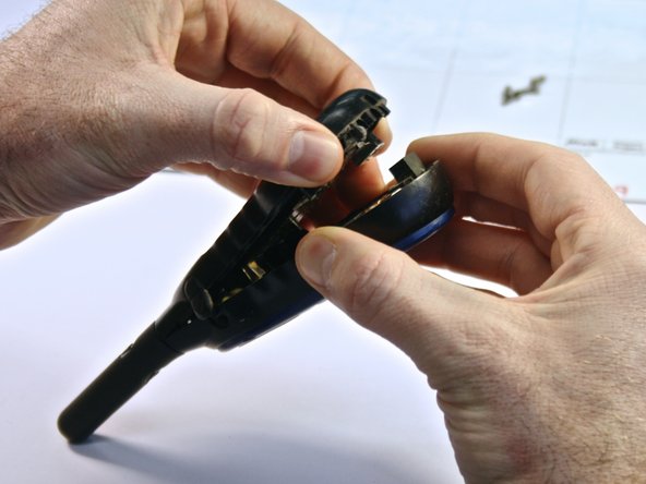
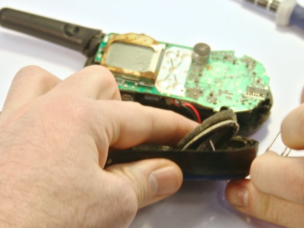
    • Gently pull the circuit board away from the front faceplate.

    • Be careful not to tug the wire connecting the circuit board to the speaker, as it is still attached to the faceplate.

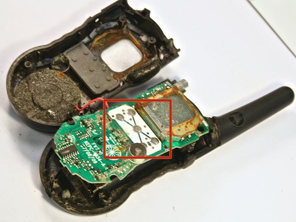
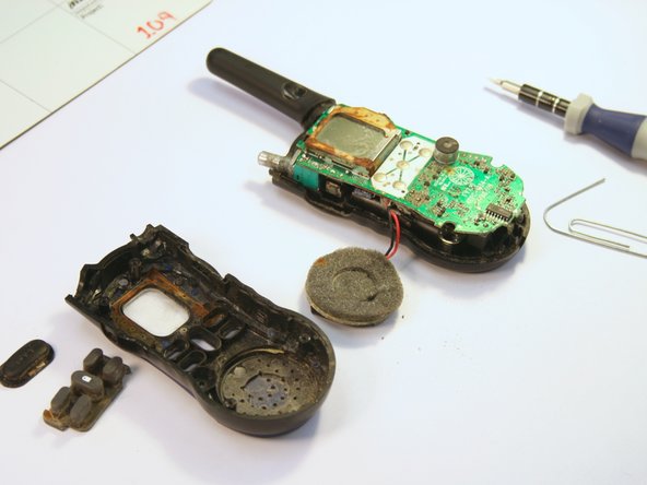
    • Do not touch the the button contacts on the circuit board (the button contacts are shown in the red box of the second picture). This can cause long-term damage to the radio unless you properly clean them (see Repairing Motorola TALKABOUT FV700 Two Way Radio Button Contacts Guide).

  9. この手順は未翻訳です。 翻訳を手伝う。

    : 手順 9、 3の画像 1 : 手順 9、 3の画像 2 : 手順 9、 3の画像 3
    • To remove the speaker from the faceplate, insert a paperclip through the front faceplate and push.

    • The speaker is glued to the front faceplate, so it may take some force to remove the speaker.

  10. この手順は未翻訳です。 翻訳を手伝う。

    : 手順 10、 3の画像 1 : 手順 10、 3の画像 2 : 手順 10、 3の画像 3
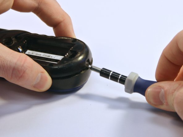
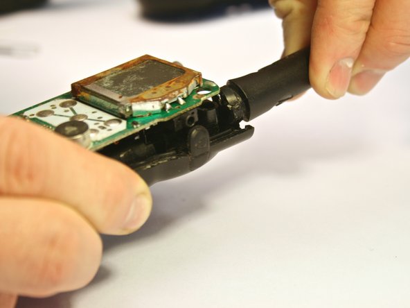
    • Now the circuit board can be removed from the back faceplate.

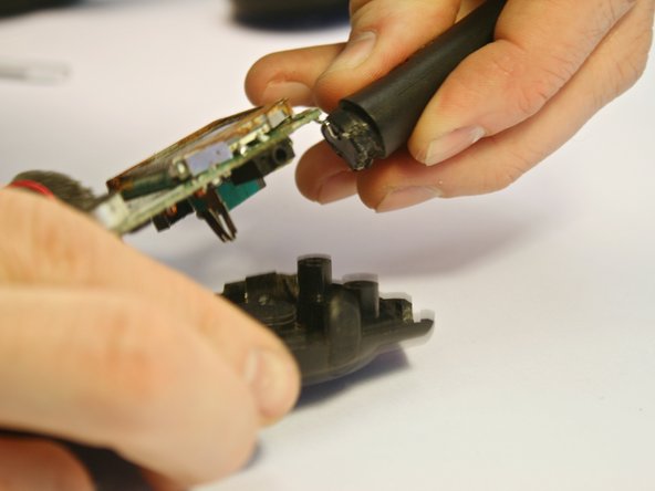
    • To do this, grip the back faceplate in one hand and the antenna in the other. Pull and twist the antenna away from the back faceplate. The circuit board should be removed with the antenna, as they are attached.

  11. この手順は未翻訳です。 翻訳を手伝う。

    : 手順 11、 1の画像 1
    • Observe the orientation of the speaker as it is removed, so that the new speaker can be installed to face the same way as the old one that you are removing.

    • You should end up with just the circuit board and speaker, as seen in the picture.

  12. この手順は未翻訳です。 翻訳を手伝う。

    : 手順 12、 1の画像 1
    • Remove the wires connecting the speaker to the circuit board with a soldering iron.

    • The new speaker wires can then be connected to the circuitboard with a soldering iron.

    • Be careful when working with a soldering iron, as it can easily cause burns.

    • Make sure the new speaker is connected in the same orientation as the old speaker.

ゴール

作成者

3人の作成者と共同で作成されました。

Kayla Brennan

メンバー登録日: 03/26/14

737 ポイント

6のガイドは作成済み

チーム

Clemson, Team 6-4, Benson Spring 2014 Clemson, Team 6-4, Benson Spring 2014人のメンバー

CLEM-BENSON-S14S6G4

3 メンバー

7のガイドは作成済み

3 件のコメント

thank you very much!!!!!!!!

deskjet27 - 返信

What glue is used to reattach speaker to front housing?

Jason Schlager - 返信

Speaker model#?...?

Jorge - 返信

コメントを追加

統計データ:

過去 24時間: 0

過去 7 日: 0

過去 30 日: 7

今までの合計 4,343