はじめに
このガイドでMotorola Moto G5 Plusのディスプレイアセンブリを取り出して、交換する方法です。
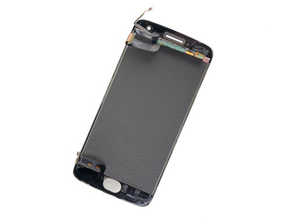
このガイドは完全体のディスプレイアセンブリを交換するためのものです。すなわち、ホームボタンを含みます。交換用パーツは 、このように見えるはずです。ディスプレイのみを購入した場合は、このガイドでは取り扱っていない、追加の解体手順に従わなければなりません。
デバイスを再組み立てする前に、バッテリーの残量を25%以下まで放電してください。充電されたリチウムイオンバッテリー は引火の原因となったり、アクシデントで穴を開けてしまうと爆発の恐れがあります。
必要な工具と部品
-
-
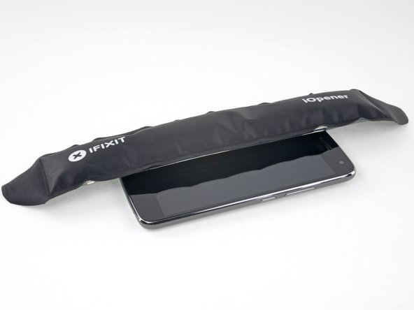
温めたiOpenerをデバイスの正面の左側端に約2分間載せます。熱くて触れない程度までの加減です。この作業により、ディスプレイに留められた接着剤を柔らかくできます。
Heat not only along the phone’s left edge, right?
I used two suction cups on the screen. Just above the finger print reader and the other near the top. Then used my heatgun set at 390 degrees. Low speed and had the wide, flat blade attachment so the heat spread to a narrow/wide area. Heated the left edge from corner to corner, then pulled up on the suction cups until I could work in a plastic triangle guitar-like-pic under the screen. Continued to heat and add another pick around the screen . Do not rush and take your time. Got the screen off and didn’t damage the adhesive too bad. Was able to reuse it. Once reassembled, I heated the screen around the edge and rubbed with a plastic tool to make sure the adhesive was working. So far so good with the adhesive. Good Luck!
strtrekbuf - 返信
-
-
-
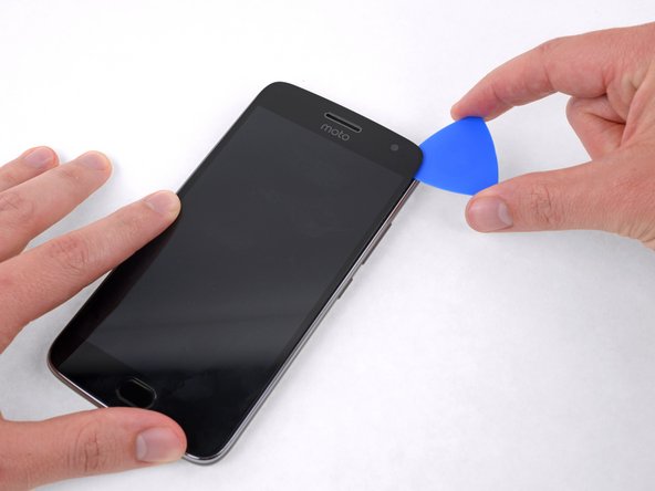
2番目と3番目の画像を参照して、ディスプレイ周辺の接着剤の幅がどれぐらいあるか確認してください。
2mm ONLY on the SIDES of the display. The top can have adhesive as far as 10mm from the edge, and at the bottom as much as 12mm. And there’s no way to cut this adhesive with the tools at 45 degrees. Once the left side is open, carefully insert the tool a little further at a time on the top and bottom, whilst attempting to keep a little pull force on the suction cup. Hard to do, and almost inevitably the on-off button will be hit at some point unless you’re really careful. The adhesive pieces are quite tough, and I used a tiny scissors to cut some of the adhesive “ropes” when the case was far enough open. A highly detailed photo of the adhesive locations top and bottom (and on both parts) would help here. This is likely the most difficult step (well, don’t know for certain, ‘cause I haven’t got further yet…), and warrants better photos and explanation IMO.
-
-
-
-
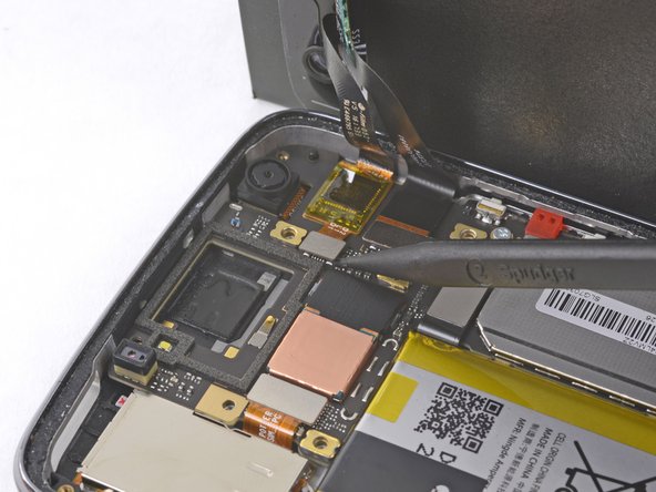
続けて、デバイスの上部と右側の接着剤を切開します。
Pues se me fastidia la pantalla al hacer esto
This is a great guide except for one thing. My screen works fine but it is separating from the phone on both sides. I need to remove it just enough to clean up the old adhesive and reattach. The instructions on repeating the steps in reverse order to replace the screen doesn't help with getting the regluing right, what kind of glue or double sided tape to use, etc …
-
-
-
イヤホンの下に留められた黒いプラスネジを2本覆っている、黄色いステッカーを外します。
Attention must be paid not to lose the small rubber gasket around the proximity sensor - I found it best to collect it with all the screws of the midframe and reinstall it at the end during re-assembly.
-
-
-
ミッドフレームから次のネジを外します。
-
3.8 mm黒いネジー16本
-
2.4 mmシルバーネジー3本
Esa placa se levanta por el otro lado, por donde estan los botones de volumen por ahi se puede levantar de una mejor manera.
-
-
-
スパッジャー平坦側を、ミッドフレームとデバイス左端の間に差し込み、ミッドフレームを所定の位置に固定している2つのクリップを慎重に取り外します。
-
-
-
デバイスからディスプレイアセンブリを外します。
-
交換用のディスプレイにタッチ機能が付いていない場合、また付いているかどうかわからない場合は、データーをバックアップ保存して、ファクトリーリセットをしてください。
If your digitizer appears to be "dead", power down the phone (which you can't because the digitizer is dead) and disconnect the battery connector by prying the connector up out of its socket (with something NONE conductive like your spudge tool) for few seconds. (It does not "slide" out, but pries straight up.) This will FORCE a cold boot and initialize the digitizer WITHOUT a factory reset, preserving all setups and all your files. :-)
-


デバイスを再組み立てする際は、これらの手順を逆の順番に従って作業を進めてください。
交換用のパーツとオリジナルのパーツを見比べてください。残りのコンポーネントを移植する必要があるか、パーツを装着する前に接着剤の裏張りを取る必要があります。
e-wasteを処理する場合は、認可済みリサイクルセンターR2を通じて廃棄してください。
修理が上手く進みませんか?トラブルシュートのヘルプには、アンサーコミュニティを参照してください。
デバイスを再組み立てする際は、これらの手順を逆の順番に従って作業を進めてください。
交換用のパーツとオリジナルのパーツを見比べてください。残りのコンポーネントを移植する必要があるか、パーツを装着する前に接着剤の裏張りを取る必要があります。
e-wasteを処理する場合は、認可済みリサイクルセンターR2を通じて廃棄してください。
修理が上手く進みませんか?トラブルシュートのヘルプには、アンサーコミュニティを参照してください。
37 の人々がこのガイドを完成させました。
以下の翻訳者の皆さんにお礼を申し上げます:
100%

Midori Doiさんは世界中で修理する私たちを助けてくれています! あなたも貢献してみませんか?
翻訳を始める ›

20 件のコメント
Thank you for the explainations. I followed the whole tutorial and I manage to fix the phone with no surprise.
Thank you. Instructions are great.
After replacing the screen, touch is offset by 125 pixels on Y axis (meaning that first registration from the top edge is at 125 px). Is there a way to get the phone to recalibrate?
Thanks
Thanks. These tips, plus the Moto G5 LCD guide solved my problem. The replacement I purchased was only for the LCD (needed to heat and remove the glass after disassembling the whole phone). Again, thanks.
does the silver plastic on back of digitizer need to be removed in order for the screen to light up on the display??
I assume there are two pieces to the screen - the glass front/digitizer/touchscreen and the LCD display itself. Is this correct? On mine I believe only the glass/digitizer is cracked since the phone works fine and has only a minor crack. This tutorial doesn’t show how to separate them. Is my understanding correct? I also need to buy the correct part and it is a bit confusing.
Ken Woolfe - 返信
Hey Ken! You are correct, there are technically two parts to the screen—the LCD/digitizer, and the glass. That said, they are glued together and extremely hard to separate! Without special tools, your likelihood of successfully replacing the glass without breaking the LCD is low. That’s why this guide just shows the removal and replacement of the whole screen assembly. If you’d like to buy the whole screen assembly (like the one in the guide) then you can do so here! If you’d prefer to just get the glass and do that repair, you might be able to find the part on another site, but unfortunately we don’t have a guide for that.
I just followed the guide with a replacement screen from ifixit and sadly it is not touch responsive though the picture is fine. I've tried wiping the cache and erasing all data from the bootloader with no success. Touch is still working with the original screen. Has anyone else had this problem?
Adam, it sounds like we may have shipped you a bad screen! I’m really sorry it’s not working for you. I suggest you get in contact with our customer support team and see if they can get you a replacement for your replacement. Just make sure you tell them that the touch on the original screen is still working!
Yes, hopefully is just a bad screen as that would be easy enough to resolve. Waiting to hear back from support now.
Alright! After a lot of googling and persistence I got it working. With the new screen connected I did a full factory reset from the bootloader, turned the phone off, disconnected the battery for ~ 30 seconds, reconnected it, switched on and hey presto, good as new :-)
That is crazy!! Excellent detective work and persistence. Thanks for keeping us updated, enjoy your new screen! :)
Had similar thing to me and after restarting phone multiple times through an org cable (it can probably also be done by holding down power button) and touch functionality was restored
shawn k -
This procedure was also required in my case. Also, I would recommend adding a step or note about applying the adhesive before plugging in the new screen. Otherwise, the directions read as though you should plug in the new screen first. This became a problem in my case because I didn’t realize that unplugging the screen to apply the adhesive would cause the screen to loose touch functionality. I was able to restore it using the battery method outlined here, but did have to go through the RMA process to get another adhesive strip to complete the repair.
After replacing my screen using the ifixit kit, there was no touch capability. I tried several things, but the only thing that worked was a factory reset. Follow the directions for external reset on this page, using recovery mode.
That’s great to know, Thomas! Thank you. It seems like you aren’t the only one who has come across this problem—I’ll add a note about this in the final step.
Hi,
I recently got the ifix it screen repir kit, and everything went fine, until I tried to type on the phone with the new screen. Like the folks above, I had an issue with the touch functionality. However, though I reset the phone, and wiped my data, the touch screen still won’t respond.
Extremely dissapointed. Please advise.
Great instructions with clear, precise photos. I found this very helpful with only one observation to add: For me, the most difficult part of this repair was affixing the new adhesive. I received an adhesive kit that comes on a peel-away template. It would have helped me, and I imagine others, if there was some demonstration of how to go about installing the new adhesive from the template on which it comes. Otherwise a great tutorial. Thanks, Mark
I was nervous about doing this. Your instructions were excellent and easy to follow the photo’s were very good they made doing the screen replacement pleasant. Thank you very much for helping with your knowledge of the subject.
re : Notification Diffuser
There is a little part that dropped out during this procedure, but not covered here.
It’s the Notification Diffuser, a little semi-translucent piece of whitish rubber about 3mm sqr.
It goes on the underside of the midframe (not in any photo here), at the top of the phone, just to the left of that centimeter wide well or hole in the motherboard, as you’re looking at the motherboard with the phone open.
It’s right near the farthest left brass “dot” in Figure 13’s photo.
It covers the Notification light.
There is mention of it on this youtube :
https://www.youtube.com/watch?v=UdenXVWz... (Not in English but you’ll here a word that sounds like “Diffuser” as he points it out.