メインコンテンツにスキップ

Motherboard Replacement

必要な工具と部品

  1. Motherboard Replacement, Fellowes T7CM Casing and Trigger Replacement: 手順 1、 1の画像 1
    • Check to make sure the shredder is not plugged in to any electrical outlet.

    • Remove the shredder from the catch basket and place the silver side down on a flat surface.

    • Place the catch basket aside as you will not be needing it for the rest of the disassembly.

  2. Motherboard Replacement: 手順 2、 1の画像 1
    • Flip the shredder silver side down and place on a flat even surface.

    • Remove the manufacturer's label in order to gain access to the hidden screw hole.

    • Locate all five of the case screws and remove them with a Phillips-Head screwdriver. The screws are located within the five marked circles in the photo. The size of the screws are 18 mm in length and head diameter of 5 mm.

  3. Motherboard Replacement: 手順 3、 1の画像 1
    • Once all of the screws are removed, slowly pull apart the casing.

    • If the casing is not separating, gently wiggle the top part of the casing from the bottom part of the casing.

    • Use Caution during this procedure to prevent from damaging any of the internal parts.

  4. Motherboard Replacement: 手順 4、 1の画像 1
    • Open the casing as shown to prevent tangling or damaging the wires.

    • Take note to how the trigger assembly is attached before removal.

    • The trigger assembly is one part and should come off all together with little to no force applied.

    • Remove the trigger assembly.

  5. Motherboard Replacement, On,  Off, Reverse Switch: 手順 5、 1の画像 1
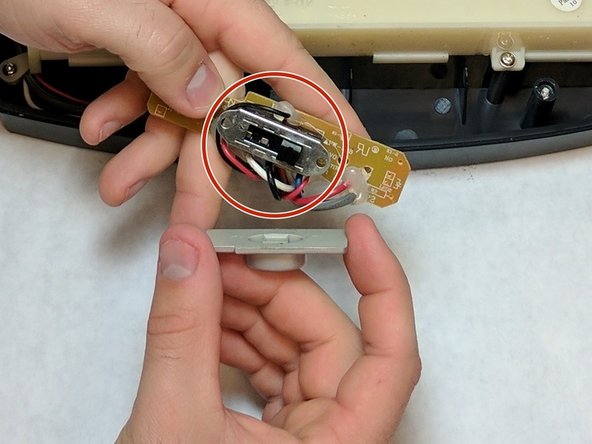
    • Unscrew both of the screws from the circuit board of the switch . Lift the circuit board away from the device. The screw length is 10 mm and the head diameter is 6 mm.

  6. Motherboard Replacement: 手順 6、 2の画像 1 Motherboard Replacement: 手順 6、 2の画像 2
    • Remove the plastic switch case.

    • After the plastic case is removed, the switch can be replaced.

    • During the switch replacement, be careful of the springs that are held in side. They can potentially come loose and get lost.

  7. Motherboard Replacement, Motherboard: 手順 7、 2の画像 1 Motherboard Replacement, Motherboard: 手順 7、 2の画像 2
    • Desolder the wires from the motherboard. Learn more about soldering componentshere!

  8. Motherboard Replacement: 手順 8、 1の画像 1
    • After all of the wires are removed, the motherboard can be lifted off and removed with ease.

終わりに

To reassemble your device, follow these instructions in reverse order.

作成者

2人の作成者と共同で作成されました。

John Wisthoff

メンバー登録日: 10/12/16

487 ポイント

3のガイドは作成済み

チーム

IUPUI, Team 2-2, Baechle Fall 2016 IUPUI, Team 2-2, Baechle Fall 2016人のメンバー

IUPUI-BAECHLE-F16S2G2

4 メンバー

16のガイドは作成済み

0 件のコメント

コメントを追加

統計データ:

過去 24時間: 0

過去 7 日: 1

過去 30 日: 4

今までの合計 761