はじめに
このガイドに従ってマザーボードを交換してください.
ディスプレイパネルは非常に壊れやすいため,この修理の途中で破損させてしまう可能性があります.接着剤を切る際は十分な熱を加え細心の注意を払ってください.また,ガラスが粉々になった場合に備えて保護メガネを着用してください.
再組立てする際にサーマルグリスを塗りなおすとSurfaceの性能が改善されることがあります.もしこれをする場合は新しいサーマルグリスと,高濃度のイソプロピルアルコール(IPA)またはサーマルグリスクリーナーを用意してください.
必要な工具と部品
-
-
スクリーンのガラスが破損している場合は、ダメージが広がって、作業中怪我をしないように、表面に保護テープを貼ります。
-
Surfaceのスクリーン上に透明な梱包テープを貼ります。完全に表面を覆ってください。
-
修理ガイドのインストラクションに沿ってベストを尽くしてください。ただし、一度ヒビが入ってしまったガラスは、作業をしている間にも割れ続ける可能性が高いため、メタル製の開口ツールでガラスをすくい出す必要があるかもしれません。
-
-
-
iOpenerを温めて、Surfaceスクリーンの右端に2分間当てます。
I have done dozens of Surface Pro tablet repairs; if your screen is cracked or chipped AT ALL, you WILL make it worse. Plan on replacing it. Even if it's not cracked or chipped, the likely hood of removing this screen without damage (LCD separation or heat marks in the corners) is very low. Ive tried everything from hot plates to heat mats and the iOpener and nothing is reliable enough. I found that using my Warner heat gun set at 800*c and working on half an edge at a time with a LOT of 91% alcohol in a drip bottle along the edge, along with a very thin guitar pick (not the ones sold here, they are too thick) is the trick to loosening the glue. Work on the side and bottom first. The top is going to be the hardest as the adhesive will stick to the wifi/bluetooth antenna and you WILL tear them (Ive had to replace a fair amount of them). There's a delicate trick to doing it, but it's too hard to describe. If you've never done this repair before, I do not recommend it; find a professional.
Hi, thanks for the information, Very valuable.
I'm about to do this because my battery and fan aren't working.
There's no way anybody can fix it properly near me. Got any other tip to try not to break the screen and or any flex?
I've done works like this on small tablets and phones, but never this pc. I'll try to go slow.
Thanks again for your experience information.
-
-
-
接着剤が使用されているレイアウト図を確認してから、次の作業に進んでください。
-
この部分は接着剤のみで、切開’しても問題ありません。
-
ディスプレイボードとフレックスケーブルが端に近い位置に装着されています。そのため開口ピックは3mm以上差し込まないでください。
-
デリケートなアンテナケーブルがスクリーンのこの位置に搭載されています。手順13のインストラクションを慎重に参照しながら作業を進めて、ダメージを与えないようにご注意ください。この位置の接着剤は厚みがあります。
The bottom red section is narrow and not as thick as the bevel indicates. I went too deep with my tool and cut through a ribbon thinking that I could send my tool as deep as the black bevel edge. its like half that.
Jesse Fair - 返信
I did a screenshot of this image to always see it while progressing through the steps and did exactly the same mistake. I read every comment in the steps below but yours only now :( On my device it's 5mm from the edge of the screen glass to the ribbon.
I cut through as well, but was able to carefully solder the edges together enough to make a connection - works fine.
L Schaffer - 返信
-
-
-
ピックをSurfaceの右端にスライドさせて、スクリーンの下の接着剤を切開します。
-
この開口ピックをデバイス右端に残しておきます。接着剤の再装着を防ぐことができます。
-
-
-
新しい開口ピックをデバイス右下に挿入し、コーナーを中心に下側に向けてスライドさせます。
-
ピックをSurface下端に沿ってスライドさせ、スクリーンの接着剤を切り取ります。
-
この開口ピックを下端に残しておくと、接着剤が再度装着するのを防ぐことができます。
Yep. I scratched the corner of the LCD with the pick. Take the warning seriously folks! It’s really easy to do.
The warning says to not insert it more than 12mm but it should be not more than 5mm. There is a ribbon/display connection at the bottom and i damaged it.
-
-
-
開口ピックで左側コーナーをスライドしてから、Surfaceの上端に沿ってスライドさせます。ピックが左端から70cm離れたところで止めます。
The right antenna is kind of P shaped (rotated 90° to the right) with the small end facing the middle. I'd suggest to stop at the middle when loosening the left antenna and to do the same thing coming from the right.
-
-
-
新たに開口ピックの先を、先ほど作業を止めたスクリーンの下に差し込みます。ベゼルの端深く挿入しないでください。
-
慎重にピックを右にスライドしながら、ピックの長辺側をベゼル下のスクリーンを固定している接着剤を切開しながら押し付けて移動します。Surfaceの上端に沿ってピックをスライドさせないでください。
-
この動作を繰り返します。ピックの先端を先ほどカットした場所に挿入し、Surfaceの上端に沿って右に転がし、ピックがSurfaceの右端から64mmのところまで移動します。
Bij mijn exemplaar bleek het onmogelijk om de bovenrand volgens de aanwijzingen los te maken. Ik heb de boel vele keren opgewarmd en ben meerdere malen met het plectrum langs de rand gegaan. Maar er beleef iets hardnekking vastplakken. Ik moest uiteindelijk de lijmverbindingen los maken zoals bij de andere randen. Achteraf bleek dat bij het gedeelte waar de antennes zaten het frame en het scherm volledig met elkaar verlijmd zaten met de antennes er tussen. Dat kostte me uiteindelijk de antennes. Gelukkig geen schade aan andere zaken. Niet zo'n grote ramp want ik kon nog antennes bestellen. Maar hou er rekening mee.
-
-
-
ゆっくりと慎重に、スクリーンアセンブリをSurfaceケースから持ち上げます。抵抗感を感じたら作業を留めて、接着剤が全て切開してあるか確認してください。
-
開口ピックを使って、残りの接着剤を全て切開します。
-
-
-
アングル付きピンセットの先端の片側を使って、"歯 "の間の隙間からEMIシールドをかき出します。
-
シールド周辺の違うポイントでもこの手順を繰り返して、シールドを外してください。
-
-
-
-
T5トルクスドライバーを使って、アンテナサポートブラケットを固定している4.5mmネジを4本外します。
This screw bit was not included in the battery replacement kit. Only Philips and Flathead were included.
This Torx bit was not included in the battery replacement kit. Only a Philips and Flathead bit
-
-
-
アンテナサポートブラケットを慎重に外します。
I had ripped through 2 of the 3 antennas when cutting through the top adhesive. Not sure how anyone removes this display without ruining at least one of them.
I saw on Reddit this post: https://www.reddit.com/r/techsupportmacg...
It works perfectly! My wifi was one that was cut. It’s now made of aluminum foil and is pulling down 147Mbps and pushing 80.88Mbps up.
A ce stade il semble important de faire attention au micro. Pour ma part, il avait un résidu de colle entre celui-ci et le support à retirer.
On my device the mic is glued to the antenna board. I'd recommend to detach it's ribbon cable from the motherboard before removing the antenna board
-
-
-
ピンセットの片側をヒートシンクを覆っているEMIシールドのコーナーにある隙間に差し込みます。
-
ピンセットを使って、EMIシールドをできるだけ曲げないように注意しながらマザーボードから外します。ここでは、まだ取り出さないでください。
-
-
-
T3トルクスドライバーを使って、ヒートシンクから2本のネジを外します。
-
バッテリーを覆っている長方形プレート上部に沿って2.4mmネジー1本
-
バッテリーを覆っている長方形プレートの下部に沿って2.2mmネジ−1本
La première vis de 2,4 est une Torx 4, pour ce qui me concerne et non pas une Torx 3.
Attention la deuxième vis est bien une TORX 3
Remarque : La boite à outil "Essentiel electronics Toolkit - Grade B (ref EU145571-1)" ne contient pas l'embout T3
Pour ma part j'ai utilisé donc le T4 en forçant un peu. Pas cool ;-(
-
-
-
プラスドライバーを使って、ファンを固定している2.4mmネジを3本外します。
-
T5トルクスドライバーを使って、ファンカバーに固定された4.4mmネジを1本外します。
These screws were in a different area on my Surface, Pro 4 bought at release. The fan was visible and attached to the heat sink. Remove the two torx screws on the fan housing. No need to remove the Philips head screws that secure the fan.
Sorry I’m super brand new to the game. I don’t know the difference between 1.5mm Torx T4 and 3.0mm Torx T4. I look under tools I need to buy, and the tool kits only say Torx T4 or T5, without the milimeters dimensions.
Je fais écho au commentaire de vennic, les longueurs indiqués en mm sont les longueurs des vis et n’impactent pas les tournevis à utiliser. Bien ranger les vis par longueur permets de mettre les bonnes vis aux bons endroits lors du remontage de l’appareil.
Cajuteq -
The fan connector on mine was held in place by a white clamp on the side closest to the middle of the chassis. The long edge toward the middle flips up to vertical. That frees up the fan connector. Likewise for the black “wire” connector right beside it.
David Hill - 返信
As previously mentioned, the fan should be disconnected (look at step 36) BEFORE you remove the fan/heat sink assembly. Ive done DOZENS of these repairs and the fan has always been part of the heat sink assembly.
I did all of this, now surface won't turn on. Any ideas?
AlejandroC - 返信
-
-
-
T5トルクスドライバーを使って、CPU周辺のヒートシンク上に留められたネジを以下の順番で1回転ずつ、外れるまで回します。
-
1番目のネジ
-
2番目のネジ
-
3番目のネジ
-
4番目のネジ
These screws were T5 Torx in mine, not T3 as in the instructions.
T5 Torx screwdriver is correct.
T4 Torx for me.
What does one turn at a time mean?
One turn for the "red" screw, one for the orange, one for the yellow, then green and now again one turn red, orange, yellow, green ... This cross pattern distributes the pressure evenly .
VauWeh -
I think I need a T6 torx screw the screwdriver is not working for these screws
Hassan Ali - 返信
-
-
-
スパッジャーの平面側先端を使って、CPUからヒートシンクをゆっくりとこじ開けて外します。
-
-
-
スパッジャーの先端をファンシールドのネジ穴に差し込みファンから持ち上げて外します。
The fan should be disconnected (look at step 36) BEFORE you remove the fan/heat sink assembly. Ive done DOZENS of these repairs and the fan has always been part of the heat sink assembly.
These instructions were correct for my Surface. The fan cover was attached to the heatsink but the fan was not.
-
-
-
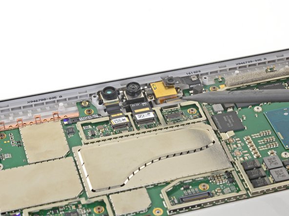
先端の鋭利なピンセットの片側を、カメラコネクタを覆っているEMIシールドのコーナーの隙間に差し込みます。
-
ピンセットを使って、マザーボードからEMIシールドをこじ開けます。変形させないようにご注意ください。
-
EMIシールドを外します。
-
-
-
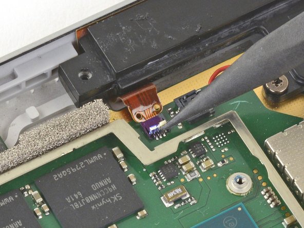
スパッジャー先端部分を使って、マザーボードから3本のカメラケーブルをこじ開けて、接続をすべて外します。
Missing the part to disconnect the ribbon to the left of the cameras, luckily, it disconnected by itself when I removed the motherboard.
Yes that's very important (white and blue socket on photo) !
I forgot to reconnect it on reassembly (unluckily, it doesn't reconnect by itself ;o)
Phil68 -
-
-
-
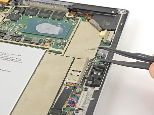
スパッジャーの先端を使って、ボリューム/電源ボタンケーブルを固定しているZIFコネクタのロックを解除します。
-
ボリューム/電源ボタンケーブルをZIFコネクタからゆっくりとスライドさせて取り出します。
While you're here, you'll want to disconnect the ZIF connector directly opposite from this one, which can be seen in the lower right of these photos, nearer the camera cable connection points. The guide doesn't mention removing that cable, but you'll need it removed before you can lift out the motherboard.
-
-
-
スピーカーワイヤとマザーボードの間にスパッ ジャーの先端を差し込み、スピーカーワイヤのコネクタの下に当てます。
-
スピーカーワイヤのコネクタをゆっくりと真上にこじ開け、マザーボードから外します。
1. the picture can be misleading
2. use the flat end instead or you might damage the plastic part of the connector. see Microsoft Surface Pro 4 左側スピーカーの交換
-
-
-
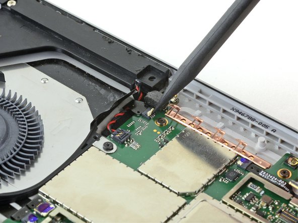
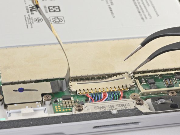
スパッジャーの先端を使って、ファンとヘッドホンジャックのZIFコネクタのロックを解除してください。
The fan should be disconnected when you removed the fan/heat sink assembly in Step 29 (which is NOT mentioned).
-
-
-
スパッジャーの先端を使って、ZIFコネクタからファンとヘッドジョンジャックのケーブルをゆっくりとスライドして外します。
The fan should be disconnected when you removed the fan/heat sink assembly in Step 29 (which is NOT mentioned).
-
-
-
T3トルクスネジドライバーを使って、ファンから次のネジを外します。
-
2.5 mmネジ(荒ネジ)ー1本
-
2.4 mmネジー2本
I didn't realize that one screw (red) here was different, and it looks like I put it in a different place during assembly, and the remaining screw, of course, did not hold. Be careful with the screws!
I have a question: can I buy a set of these screws for Surface Pro 4 to change the spoiled ones? I noticed that sometimes they get damaged on top and it is difficult to screw them on afterwards.
-
-
-
ピンセットの片側をmicroSDカードリーダーのケーブルとコネクタの端の隙間に差し込みます。
-
ピンセットを使って、EMIシールドをこじ開けて、マザーボードから外します。曲げないようにご注意ください。
-
シールドを取り出します。
-
-
-
スパッジャーの平らな方を使って、microSDカードリーダーのコネクタをまっすぐ上に持ち上げてソケットから外します。
-
microSDカードリーダーケーブルを持ち上げ、充電アセンブリを覆っているEMIシールドの邪魔にならないようにします。
It's probably best to remove the microSD card reader at this point. The guide never states to remove it, but it eventually disappears from the photos. Two T5 screws are all that are holding it down. Easier to take those out and remove the assembly than to try to remove the EMI shield underneath while also holding the ribbon cable out of the way.
Not necessary to remove the reader. When reinserting the motherboard, you can slide it easily enough underneath it. It may make it easier, but isn't necessary.
A ce stade, la nappe était coller sur le blindage. Pour ne pas trop plier la nappe, j'ai poussé la spatule. La colle n'était pas trop résistante.
-
-
-
充電アセンブリケーブルのコネクタを覆っているEMIシールドの端の隙間に、ピンセットの片側を差し込みます。
-
ピンセットを使って、EMIシールドを曲げないように、できるだけマザーボードからこじ開けます。
-
シールドを外します。
-
-
-
スパッジャーの平面側先端を使って、充電アセンブリケーブルのコネクタを固定しているロックを跳ね上げます。
-
-
-
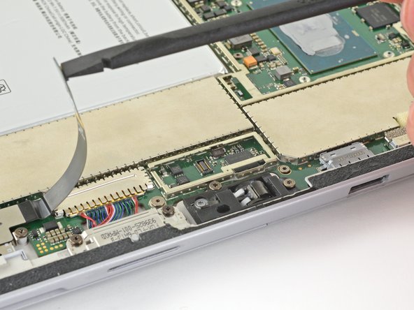
プロセッサと右スピーカーの間にあるZIFコネクタのロックを解除するには、スパッジャーの先端部分を使います。
-
ZIFコネクタからケーブルの接続を外します。
This one broke during reassembling, so I could not fix the connector properly. I tried to find out what it is, but the only hint I found was, that it is some kind of antenna. I could not find out what kind of antenna. Anyway, after completion everything I needed worked fine: Bluetooth and Wireless LAN. I appreciate any hint about the purpose of this antenna.
That's my question too
Mj Ro -
Perhaps one of the two WiFi frequencies (2.4 or 5 GHz)?
Phil68 -
-
-
-
右側スピーカーワイヤとマザーボードの間に、スパッジャーの先端をスライドして差し込み、スピーカーワイヤのコネクタに当たるまで、こじ開けます。
-
スピーカーワイヤのコネクタを慎重に真上にこじ開け、マザーボードから外します。
-
-
-
T3トルクスドライバーを使って、ファンとマザーボードから次のネジを外します。
-
長さ2.4 mmネジー10本
-
長さ2.2 mmネジー2本
-
右側スピーカーを固定しているT5トルクスドライバーを使って、2本のネジを外します。
-
長さ4.2 mmネジー1本
-
長さ6.0 mmネジー1本
Use a T5 Torx screwdriver to remove screw in left and right speaker.
BE CAREFUL! Use a T5 Torx screwdriver to remove an ADDITIONAL screw on the top corner of the right speaker. It should not take a tremendous amount of force to remove the speaker.
This screw is in the frame of the SP4. Mine was a T3.
An additional screw has been marked up and added to the original photo regarding the issues with the right fan removal. Thanks to the community for the feedback!
-
-
-
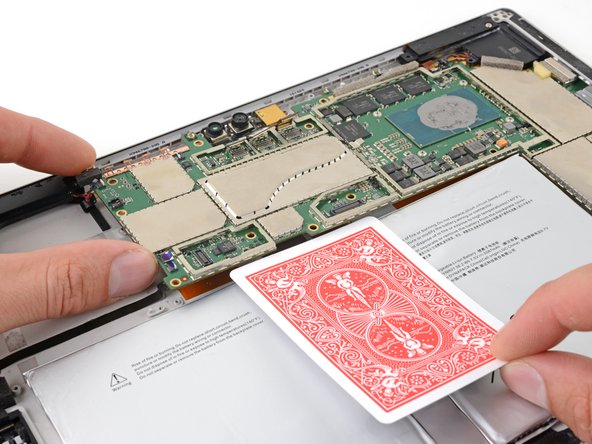
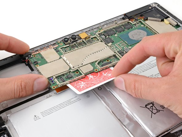
マザーボードの左端をわずかに持ち上げます。
-
バッテリーコネクターとマザーボードの間にトランプなどを差し込んでください。
-
-
-
右スピーカーボックスの細い部分をつまみ、少し持ち上げてください。
-
右側スピーカーをスライドさせながら筐体から外します。
-
右側スピーカーを取り出します。
I didn’t read about the other T5 (about 6 mm) holding down the right speaker. It needs to be removed prior to this step.
You also need to remove a screw in the top right corner of the speaker
Yup there is an unmentioned t5 screw that the other comments catch
-
-
-
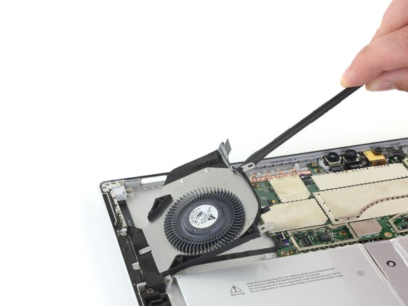
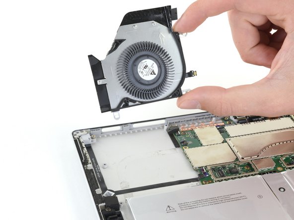
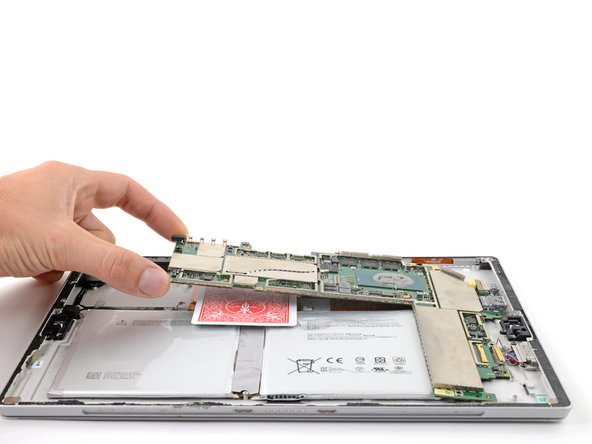
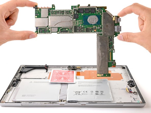
マザーボードを取り外すには、まず左側を約30度の角度になるまで持ち上げてください。
-
マザーボード上のI/Oポートを開口部からゆっくりとスライドさせ、マザーボードを取り外してください。
There seems to be an additional ZIF connector by the Left most camera that also needs to be disconnected. Beware.
Also, the micro SD reader obstructs a little bit (at bottom right )as you remove the motherboard.
-


再組立てする際は上記の手順を逆順にして行ってください.
電気電子機器廃棄物(E-waste)は地方公共団体が定めるガイドラインに従って、適切な方法で処理をしてください。
修理がうまくいきませんでしたか?basic troubleshootingを試してみるか,アンサーズコミュニティに相談してみてください.
再組立てする際は上記の手順を逆順にして行ってください.
電気電子機器廃棄物(E-waste)は地方公共団体が定めるガイドラインに従って、適切な方法で処理をしてください。
修理がうまくいきませんでしたか?basic troubleshootingを試してみるか,アンサーズコミュニティに相談してみてください.
3 の人々がこのガイドを完成させました。
以下の翻訳者の皆さんにお礼を申し上げます:
100%

これらの翻訳者の方々は世界を修理する私たちのサポートをしてくれています。 あなたも貢献してみませんか?
翻訳を始める ›

3 件のコメント
awesome info; used it to strip four "broken" tablets and reassemble as three working tablets (Schottky diodes and bad batteries)
Un genio, paso por paso, muy didactico como pracico! Gracias por toda tu informacion me he dado cuenta que es un trabajo muy meticuloso y no es para andar a la apuradas! Realmente muchas gracias
If I have a screen protector on the screen should I remove it? Will it interfere with the heating process?
IronJoker - 返信