このバージョンは誤った内容を含んでいる可能性があります。最新の承認済みスナップショットに切り替えてください。
必要な工具と部品
-
この手順は未翻訳です。 翻訳を手伝う。
-
Locate the two 5.08mm T5 Torx screws. The two screws will be located on the left and right sides in the kickstand.
-
Make sure when removing the screws to be careful to prevent stripping of the head.
-
With all the screws removed gently wiggle the stand side to side until the lever in the middle is free, releasing the stand.
-
-
-
この手順は未翻訳です。 翻訳を手伝う。
-
Next, remove the ten 5.92mm T5 torx screws located underneath the kickstand.
-
Remove the seven 5.87mm T5 torx screws located under the camera casing. There is a sticker covering the second screw from the left.
-
Disconnect the rear cover from the main shell of the system by loosening it with a spudger where the gaps exist.
-
Continue working your way around to each corner and loosen the snap-ons on each side until the rear cover comes off.
-
-
この手順は未翻訳です。 翻訳を手伝う。
-
Rotate the device 180 degrees so that the bottom of the device is facing you.
-
A ribbon connects the battery on the rear cover, to the motherboard. Slowly lift the bottom of the rear cover up until you can see the ribbon.
-
Use a spudger to push the ribbon away from the motherboard and parallel to the motherboard in order to remove the ribbon.
-
Separate the rear cover by lifting it up away from the main system.
-
-
この手順は未翻訳です。 翻訳を手伝う。
-
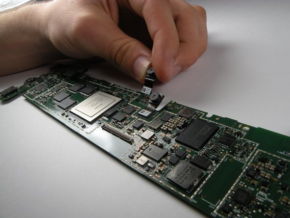
Unscrew the seven 3.61mm T5 Torx screws from the motherboard.
-
Use the plastic opening tool to lift the lab and unplug the orange ribbon on the right side of the motherboard.
-
Use the plastic opening tool to lift the tab connecting the orange ribbon to the motherboard.
-
Use a plastic opening tool to lift the display and digitizer cable plug from the middle of the motherboard.
-


4 の人々がこのガイドを完成させました。
チーム

Cal Poly, Team 17-23, Forte Winter 2013 Cal Poly, Team 17-23, Forte Winter 2013人のメンバー
CPSU-FORTE-W13S17G23
5 メンバー
17のガイドは作成済み