メインコンテンツにスキップ

このバージョンは誤った内容を含んでいる可能性があります。最新の承認済みスナップショットに切り替えてください。

必要な工具と部品

  1. この手順は未翻訳です。 翻訳を手伝う。

    : 手順 1、 2の画像 1 : 手順 1、 2の画像 2
    • Flip the projector onto its back and unscrew the nine 15mm screws using the Phillips #0 screw driver.

  2. この手順は未翻訳です。 翻訳を手伝う。

    : 手順 2、 1の画像 1
    • Flip the projector right side up and unscrew the two 12mm screws on the light bulb panel located at the rear of the projector with a Phillips #0 screw head.

    • The bottom right panel screw does not come completely out the panel door.

  3. この手順は未翻訳です。 翻訳を手伝う。

    : 手順 3、 2の画像 1 : 手順 3、 2の画像 2
    • Using your hands, gently pry the top and bottom of the projector casing apart.

  4. この手順は未翻訳です。 翻訳を手伝う。

    : 手順 4、 2の画像 1 : 手順 4、 2の画像 2
    • Use the plastic opening tool to gently disengage the black clip housing from the ribbon cable.

    • Once the ribbon cable is disengaged gently pull the cable off the motherboard.

    • Once the housing is disengaged, the ribbon cable should slide out easily. Do not pull too hard on the ribbon cable as it is very fragile.

  5. この手順は未翻訳です。 翻訳を手伝う。

    : 手順 5、 3の画像 1 : 手順 5、 3の画像 2 : 手順 5、 3の画像 3
    • Unscrew the three 7 mm screws from the motherboard with the Phillips #0 screw driver.

    • Once loose, lift the motherboard off of the lens casing, and move it away from the workspace.

    • Be sure not to damage any of the wires atached to the motherboard.

  6. この手順は未翻訳です。 翻訳を手伝う。

    : 手順 6、 3の画像 1 : 手順 6、 3の画像 2 : 手順 6、 3の画像 3
    • Unscrew the four 15mm Phillips screws using the Phillips #0 screw driver.

    • Unscrew the two 12mm Phillips screws using the Phillips #0 screw driver.

    • Gently remove the entire lens casing from it's position.

  7. この手順は未翻訳です。 翻訳を手伝う。

    : 手順 7、 3の画像 1 : 手順 7、 3の画像 2 : 手順 7、 3の画像 3
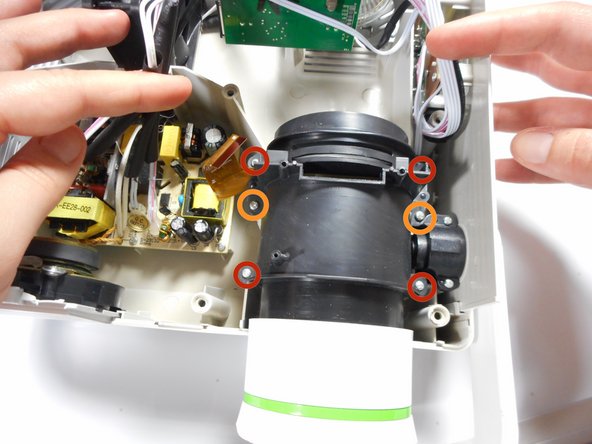
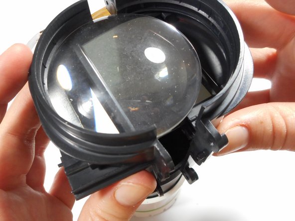
    • Using the plastic opening tool, slightly separate the casing holding the large lens in place.

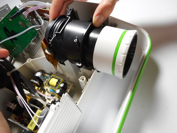
    • Separate the casing completely from the inner lens using your hands.

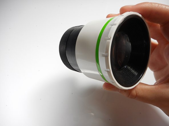
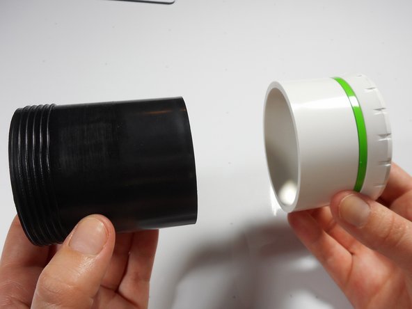
    • This should release the outer lens and it's immediate casing.

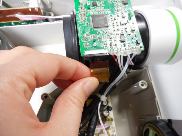
    • As you separate the outer casing, the lens and digital display box may fall out of their encasement.

    • Although there are threads connecting the outer lens casing and the inner lens casing, do not be fooled. The outer lens casing cannot be disconnected by unscrewing it.

  8. この手順は未翻訳です。 翻訳を手伝う。

    : 手順 8、 3の画像 1 : 手順 8、 3の画像 2 : 手順 8、 3の画像 3
    • Unscrew the four 8mm Phillips screws at the base of the outer lens casing using the Phillips #0 screw driver.

    • Separate the white outer casing from the black outer casing.

  9. この手順は未翻訳です。 翻訳を手伝う。

    : 手順 9、 2の画像 1 : 手順 9、 2の画像 2
    • Using your finger, gently push the lens out of its white encasement.

    • The outer lens is now free and ready for replacement.

ゴール

2 の人々がこのガイドを完成させました。

作成者

6人の作成者と共同で作成されました。

Stephanie

メンバー登録日: 01/08/15

276 ポイント

3のガイドは作成済み

チーム

Cal Poly, Team 18-3, Maness Winter 2015 Cal Poly, Team 18-3, Maness Winter 2015人のメンバー

CPSU-MANESS-W15S18G3

3 メンバー

4のガイドは作成済み

0 件のコメント

コメントを追加

統計データ:

過去 24時間: 0

過去 7 日: 3

過去 30 日: 8

今までの合計 3,095