メインコンテンツにスキップ

このバージョンは誤った内容を含んでいる可能性があります。最新の承認済みスナップショットに切り替えてください。

必要な工具と部品

  1. この手順は未翻訳です。 翻訳を手伝う。

    : 手順 1、 2の画像 1 : 手順 1、 2の画像 2
    • Remove the four rubber caps from the back by using the Phillips #00 screwdriver.

  2. この手順は未翻訳です。 翻訳を手伝う。

    : 手順 2、 1の画像 1
    • Remove the four screws holding the cover in place by using the Phillips #00 screwdriver.

  3. この手順は未翻訳です。 翻訳を手伝う。

    : 手順 3、 2の画像 1 : 手順 3、 2の画像 2
    • Remove the back cover from the device by separating the back cover along its seam.

    • Slowly lift the cover—the speaker is screwed onto the back cover and is connected to the circuit board.

  4. この手順は未翻訳です。 翻訳を手伝う。

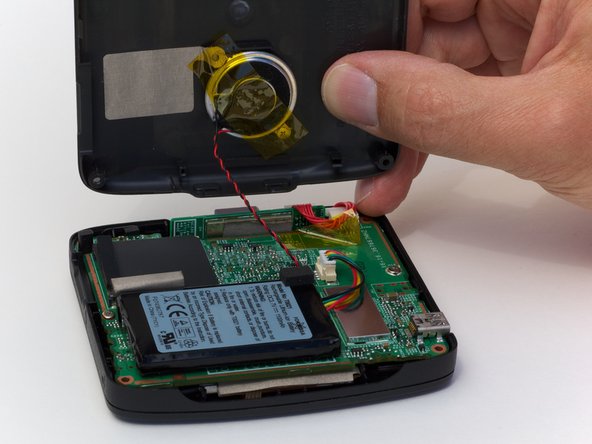
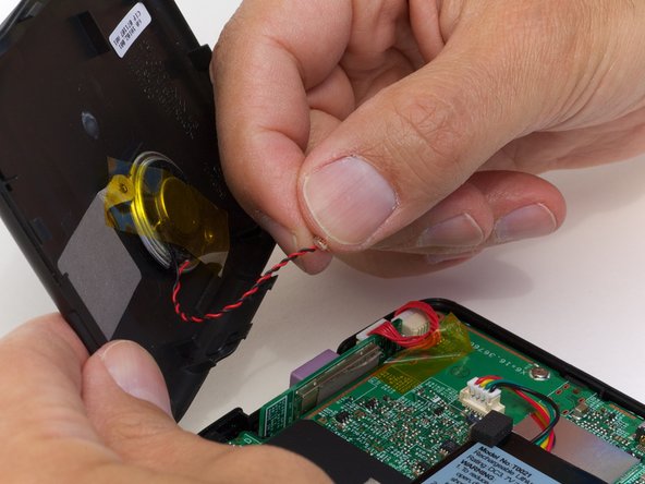
    : 手順 4、 2の画像 1 : 手順 4、 2の画像 2
    • Pull the speaker cord, horizontally, by its base, away from the motherboard.

    • When reassembling, make sure that you plug the terminal in the same way. The black wire should be on the side farthest from the battery.

  5. この手順は未翻訳です。 翻訳を手伝う。

    : 手順 5、 1の画像 1
    • Remove the two screws on that are located on opposite sides of the board.

  6. この手順は未翻訳です。 翻訳を手伝う。

    : 手順 6、 1の画像 1
    • Lift up the circuit board and disconnect the GPS wire, pulling horizontally from its connector port.

  7. この手順は未翻訳です。 翻訳を手伝う。

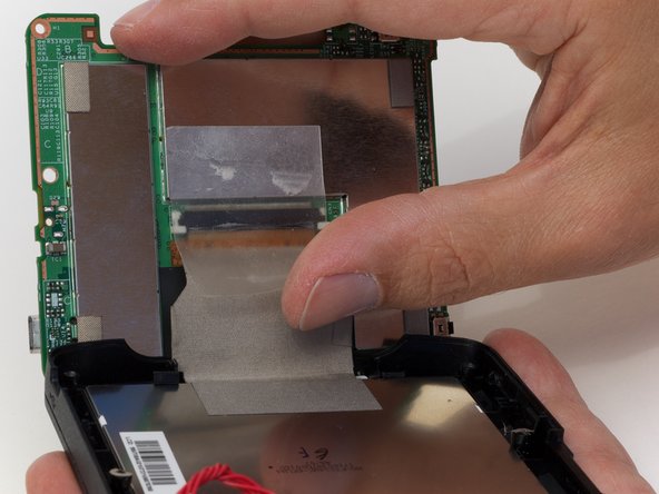
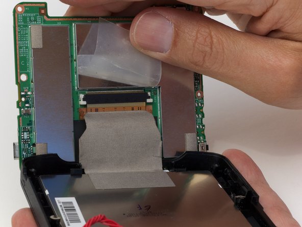
    : 手順 7、 2の画像 1 : 手順 7、 2の画像 2
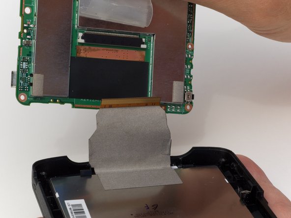
    • Peel back the tape securing the display connector to the logic board.

  8. この手順は未翻訳です。 翻訳を手伝う。

    : 手順 8、 1の画像 1
    • Remove the display connector from the device.

    • Do not pull on the cable because you may damage it. Instead, try to pull as closely as you can to the plug.

  9. この手順は未翻訳です。 翻訳を手伝う。

    : 手順 9、 2の画像 1 : 手順 9、 2の画像 2
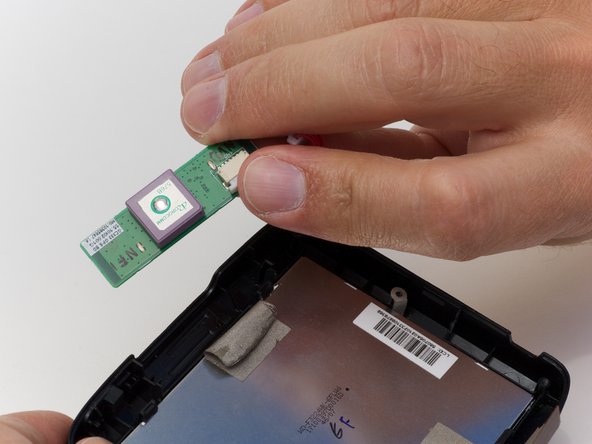
    • Carefully flip the circuit board out so you can get to the sensor easily.

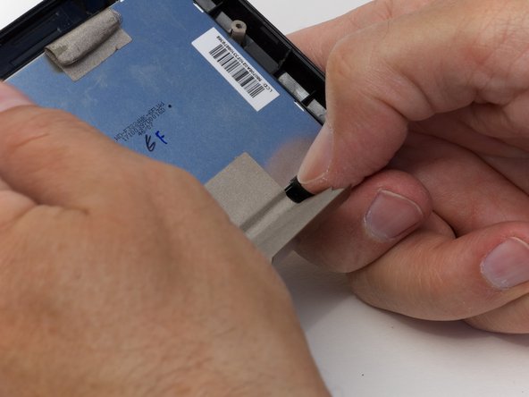
    • Remove the tape holding the sensor to the display and take out the sensor.

  10. この手順は未翻訳です。 翻訳を手伝う。

    : 手順 10、 3の画像 1 : 手順 10、 3の画像 2 : 手順 10、 3の画像 3
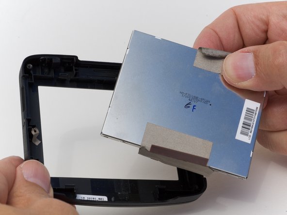
    • Undo the 4 clasps holding the display in place.

    • Pop the display from the front cover.

ゴール

ある他の人がこのガイドを完成しました。

作成者

4人の作成者と共同で作成されました。

Ross Light

メンバー登録日: 04/12/10

217 ポイント

6のガイドは作成済み

コメント 1 件

In order to remove the rubber plugs hiding the 4 screws, I found that a straight pin angled into the top of the plug can be used to lift them easily straight out and the plug is unharmed.

With the screws out, the back did not budge. I used the thinest blade screw driver in my jeweler's set to pry the case open and pushed on the plastic catches, one on each side that were holding it closed. They are visible in the photo of the back off.

Jomar - 返信

コメントを追加

統計データ:

過去 24時間: 2

過去 7 日: 9

過去 30 日: 11

今までの合計 3,453