メインコンテンツにスキップ

このバージョンは誤った内容を含んでいる可能性があります。最新の承認済みスナップショットに切り替えてください。

必要な工具と部品

  1. この手順は未翻訳です。 翻訳を手伝う。

    : 手順 1、 2の画像 1 : 手順 1、 2の画像 2
    • Start by turning the computer around, and remove this #0 Phillips Screw.

    • There may or may not be a Phillips #0 screw here, depending on whether or not the computer has ever been serviced.

  2. この手順は未翻訳です。 翻訳を手伝う。

    : 手順 2、 3の画像 1 : 手順 2、 3の画像 2 : 手順 2、 3の画像 3
    • Now lift these two clips, and slowly pivot the case up.

    • You can now seperate the top of the computer from the rest of the machine.

  3. この手順は未翻訳です。 翻訳を手伝う。

    : 手順 3、 3の画像 1 : 手順 3、 3の画像 2 : 手順 3、 3の画像 3
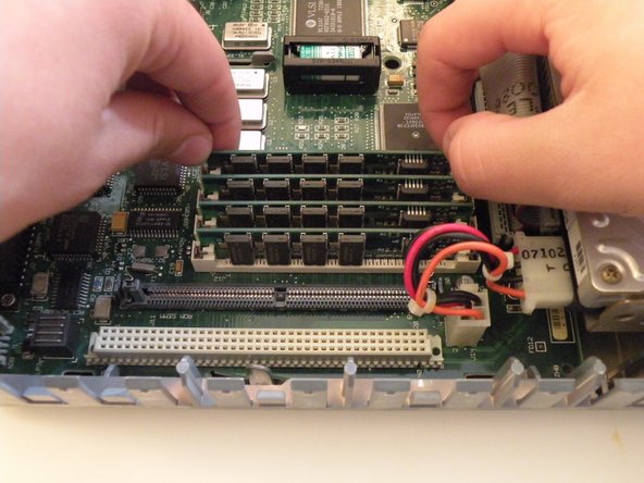
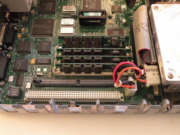
    • The IIsi uses 4 30-Pin SIMMs (Installed in pairs of 2) for a maximum ram capacity of 65MB. It has 1MB soldered to the logic board as well.

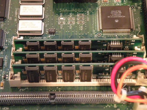
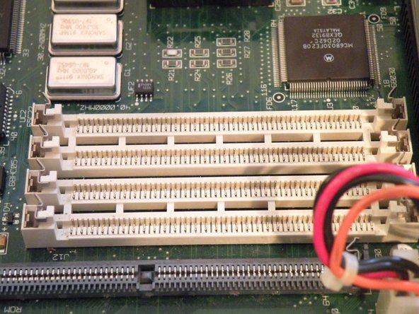
    • Start with this SIMM. Push these 2 metal tabs outward, then push the ram forward. It can then be lifted out. You have to remove the SIMMs in order, starting with the one you just removed. You can then work your way through all of them.

  4. この手順は未翻訳です。 翻訳を手伝う。

    : 手順 4、 3の画像 1 : 手順 4、 3の画像 2 : 手順 4、 3の画像 3
    • 1st Photo: The RAM Module

ゴール

4 の人々がこのガイドを完成させました。

作成者

5人の作成者と共同で作成されました。

Chris Green

メンバー登録日: 10/11/09

37,014 ポイント

49のガイドは作成済み

チーム

Master Techs Master Techs人のメンバー

Community

322 メンバー

2,539のガイドは作成済み

0 件のコメント

コメントを追加

統計データ:

過去 24時間: 2

過去 7 日: 8

過去 30 日: 12

今までの合計 2,223