メインコンテンツにスキップ

このバージョンは誤った内容を含んでいる可能性があります。最新の承認済みスナップショットに切り替えてください。

必要条件のみ
この修理ガイドは、他のガイドの前提条件として使用されます。それ自体は不完全で、単独で使用されることはありません。

必要な工具と部品

  1. , アクセスドア: 手順 1、 1の画像 1
    • ケースを閉じたまま、Unibodyを裏返しにして水平に置きます。

    • アクセスドアのリリース用ラッチの溝側を押し込んで、出てきた先端をつかみます。 リリース用ラッチが垂直になるまで持ち上げます。

  2. : 手順 2、 1の画像 1
    • これで、アクセスドアを持ち上げて、Unibodyから取り外せるはずです。

  3. , バッテリー: 手順 3、 1の画像 1
    • 作業を開始する前に、アクセスドアのリリースラッチが垂直になっているか確認してください。

    • 白のプラスチック製タブを掴み、バッテリーを引き上げ、Unibodyから取り出します。

  4. , 下部ケース: 手順 4、 1の画像 1
    • 下部ケースをシャーシに固定している次の8本のネジを外します:

    • 3mmプラスネジ 1本

    • 13.5mmプラスネジ 3本

    • 3.5mmプラスネジ 4本

  5. : 手順 5、 1の画像 1
    • 両手を使って、上部ケースから下部ケースを持ち上げて外します。

  6. , ディスプレイアセンブリ: 手順 6、 1の画像 1
    • カメラケーブルのソケットからケーブル オスをまっすぐ引き抜いて、カメラケーブルの接続を外します。

    • ソケットからケーブルを外す際は、ケーブルを引き上げないようにご注意ください。

  7. : 手順 7、 2の画像 1 : 手順 7、 2の画像 2
    • 光学ドライブの溝からカメラデータケーブルを巻き戻して外します。

  8. : 手順 8、 2の画像 1 : 手順 8、 2の画像 2
    • カメラのデーターケーブルと右側スピーカーを上部ケースに固定している次のネジを外します。

    • 9.9 mm 一部分がネジ状のプラスネジ

    • 9.6 mm ネジ状のプラスネジ

    • 4 mm プラスネジ−1本

    • カメラケーブルのブラケットをサブウーファーの下からスライドして取り出し、デバイスから外します。

    • iSightケーブルにはアイレットが付いていて、これらの画像中にある一番左のネジが通っています。

  9. : 手順 9、 2の画像 1 : 手順 9、 2の画像 2
    • ディスプレイデーターケーブルのロックに固定されたプラスチックのプルタブを摘んで、デバイス本体のDC-in側に向けて回転させます。

    • ディスプレイデータケーブルのコネクタをソケットからまっすぐ引き抜きます。

    • コネクタをソケットからまっすぐ引き抜いて、外します。

  10. : 手順 10、 2の画像 1 : 手順 10、 2の画像 2
    • ディスプレイデータケーブルブラケットから次の2本のネジを外します:

    • 7mmプラスネジ 1本

    • 5mmプラスネジ 1本

    • 上部ケースからディスプレイデータケーブルブラケットを持ち上げます。

  11. : 手順 11、 1の画像 1
    • ディスプレイと上部ケースを固定している外側6mmトルクスネジを両側で2本ずつ、計4本外します。

  12. : 手順 12、 1の画像 1
    • MacBookを開いて、ディスプレイが上部ケースに対して垂直になるようにします。

    • 画像のようにMacBook本体を作業台の上に配置します。

    • ディスプレイと上部ケースを同時に左側で固定しながら、下側ディスプレイのブラケットより6mmトルクスネジを外します。

  13. : 手順 13、 1の画像 1
    • 左手でディスプレイと上部ケース両方を固定してください。 そうしなければ外れれたディスプレイ/上部ケースが落下し、各コンポーネントが損傷する可能性があります。

    • 上部ケースにディスプレイを固定している最後の6mmトルクスネジを外します。

  14. : 手順 14、 3の画像 1 : 手順 14、 3の画像 2 : 手順 14、 3の画像 3
    • 上部ケースを右手で掴み、ディスプレイの上部に向けて少し回転させ、上部ディスプレイのブラケットが上部ケース端から外れるようにします。

    • ディスプレイを上部ケースからわずかにずらします。

    • ディスプレイを上部ケースから持ち上げます。ブラケットやケーブルが挟まれていないかご注意ください。

  15. この手順は未翻訳です。 翻訳を手伝う。

    : 手順 15、 2の画像 1 : 手順 15、 2の画像 2
    • Some 2.0 GHz A1278 MacBook Unibody logic boards do not have the necessary socket installed to accept the keyboard backlight ribbon cable attached to the upper case. The first and second pictures show logic boards with and without the socket installed, respectively. If your logic board does not have the backlight ribbon cable socket installed, the keyboard will work but the keys will not light up.

    • If your logic board does not have the socket installed to accept the keyboard backlight ribbon cable and you are installing a backlit upper case, simply tuck the keyboard backlight ribbon cable out of the way when you reinstall the logic board into the upper case.

  16. この手順は未翻訳です。 翻訳を手伝う。

    : 手順 16、 1の画像 1
    • Remove the single Phillips screw securing the hard drive bracket to the chassis.

    • This screw is captive to the hard drive bracket.

  17. この手順は未翻訳です。 翻訳を手伝う。

    : 手順 17、 1の画像 1
    • Lift the hard drive by its pull tab enough to grab and remove the retaining bracket.

    • Lift the hard drive out of the chassis, minding the cable attaching it to the computer.

  18. この手順は未翻訳です。 翻訳を手伝う。

    : 手順 18、 1の画像 1
    • Remove the hard drive from its cable by pulling the cable connector straight away from the drive.

  19. この手順は未翻訳です。 翻訳を手伝う。

    : 手順 19、 1の画像 1
    • Remove the four 10.3 mm Phillips screws securing the mid wall to the upper case.

  20. この手順は未翻訳です。 翻訳を手伝う。

    : 手順 20、 1の画像 1
    • Lift the mid wall out of the upper case.

  21. この手順は未翻訳です。 翻訳を手伝う。

    : 手順 21、 1の画像 1
    • Remove the following three screws securing the fan to the upper case:

    • Two 5 mm Phillips screws.

    • One 7 mm Phillips screw.

  22. この手順は未翻訳です。 翻訳を手伝う。

    : 手順 22、 3の画像 1 : 手順 22、 3の画像 2 : 手順 22、 3の画像 3
    • Use a spudger to pry the fan connector straight up and out of its socket on the logic board.

    • It is useful to twist the spudger axially from beneath the fan cable wires to release the connector.

    • The fan socket and the fan connector can be seen in the second and third pictures. Be careful not to break the plastic fan socket off the logic board as you use your spudger to lift the fan connector straight up and out of its socket. The layout of the logic board shown in the second picture may look slightly different than your machine but the fan socket is the same.

  23. この手順は未翻訳です。 翻訳を手伝う。

    : 手順 23、 1の画像 1
    • Lift the fan out of the upper case.

  24. この手順は未翻訳です。 翻訳を手伝う。

    : 手順 24、 1の画像 1
    • Using the flat end of a spudger, pry the subwoofer connector straight up off the logic board.

  25. この手順は未翻訳です。 翻訳を手伝う。

    : 手順 25、 1の画像 1
    • Remove the single Phillips screw securing the subwoofer to the upper case.

  26. この手順は未翻訳です。 翻訳を手伝う。

    : 手順 26、 1の画像 1
    • The subwoofer is still connected to the right speaker, so don't completely remove it just yet.

    • Lift the subwoofer off the optical drive, and set it above the computer.

  27. この手順は未翻訳です。 翻訳を手伝う。

    : 手順 27、 1の画像 1
    • Use a spudger to pry the optical drive connector straight up off the logic board.

  28. この手順は未翻訳です。 翻訳を手伝う。

    : 手順 28、 1の画像 1
    • Use the flat end of a spudger to pry the hard drive cable connector straight up off the logic board.

  29. この手順は未翻訳です。 翻訳を手伝う。

    : 手順 29、 2の画像 1 : 手順 29、 2の画像 2
    • Remove the three 2.5 mm Phillips screws securing the optical drive to the upper case.

  30. この手順は未翻訳です。 翻訳を手伝う。

    : 手順 30、 1の画像 1
    • Lift the optical drive from its right edge and pull it out of the computer.

  31. この手順は未翻訳です。 翻訳を手伝う。

    : 手順 31、 2の画像 1 : 手順 31、 2の画像 2
    • Peel the hard drive cable from the adhesive securing it to the upper case, and maneuver the plastic retaining block out of the upper case.

    • The hard drive cable and the plastic retaining block are attached together.

  32. この手順は未翻訳です。 翻訳を手伝う。

    : 手順 32、 3の画像 1 : 手順 32、 3の画像 2 : 手順 32、 3の画像 3
    • Peel back the small piece of black tape covering the right speaker cable.

    • Use the tip of a spudger to pry the right speaker up off the adhesive securing it to the upper case.

    • Lift the subwoofer and right speaker assembly out of the upper case.

  33. この手順は未翻訳です。 翻訳を手伝う。

    : 手順 33、 2の画像 1 : 手順 33、 2の画像 2
    • Use the tip of a spudger to flip up the locking lever to release the IR sensor ribbon cable from its socket.

    • Pull the IR sensor ribbon cable straight away from the logic board.

  34. この手順は未翻訳です。 翻訳を手伝う。

    : 手順 34、 1の画像 1
    • Use the flat end of a spudger to pry the trackpad connector straight up off the logic board.

  35. この手順は未翻訳です。 翻訳を手伝う。

    : 手順 35、 2の画像 1 : 手順 35、 2の画像 2
    • Using the tip of a spudger, flip up the keyboard ribbon cable retaining flap.

    • Pull the keyboard ribbon cable straight out of its socket.

  36. この手順は未翻訳です。 翻訳を手伝う。

    : 手順 36、 2の画像 1 : 手順 36、 2の画像 2
    • Remove the two 5 mm Phillips screws securing the keyboard flex bracket to the upper case.

    • Lift the keyboard flex bracket out of the upper case.

  37. この手順は未翻訳です。 翻訳を手伝う。

    : 手順 37、 2の画像 1 : 手順 37、 2の画像 2
    • Remove the single Phillips screw securing the battery cable cover to the upper case.

    • Remove the battery cable cover from the upper case.

  38. この手順は未翻訳です。 翻訳を手伝う。

    : 手順 38、 1の画像 1
    • Use a spudger to pry the battery level indicator cable connector straight up off the logic board.

  39. この手順は未翻訳です。 翻訳を手伝う。

    : 手順 39、 1の画像 1
    • Disconnect the battery cable connector by pulling it straight away from the logic board.

    • If you cannot grasp the cable with your fingers, a spudger and tweezers may be helpful for removal.

  40. この手順は未翻訳です。 翻訳を手伝う。

    : 手順 40、 2の画像 1 : 手順 40、 2の画像 2
    • Remove the two 4mm Phillips screws securing the bottom case clip to the upper case.

    • Lift the bottom case clip out of the upper case.

  41. この手順は未翻訳です。 翻訳を手伝う。

    : 手順 41、 1の画像 1
    • Use the tip of a spudger to release the microphone from the upper case.

  42. この手順は未翻訳です。 翻訳を手伝う。

    : 手順 42、 2の画像 1 : 手順 42、 2の画像 2
    • Remove the following five screws securing the logic board to the upper case:

    • Four 3 mm Phillips screws.

    • One 3.5 mm Phillips screw.

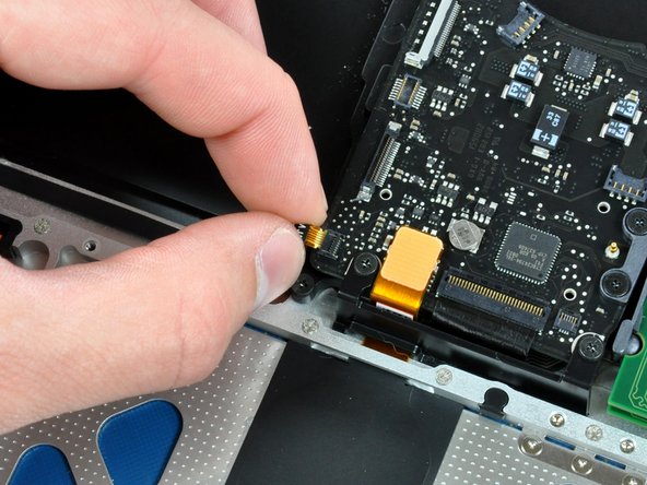
    • Remove the two 7 mm Phillips screws securing the DC-in board to the upper case.

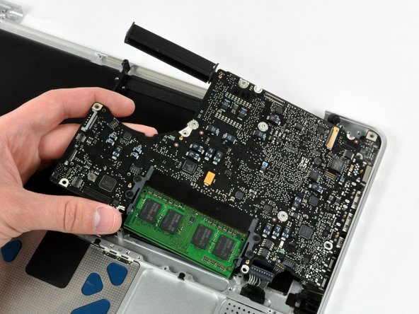
    • Lift the logic board from its left edge and pull it out of the upper case.

  43. この手順は未翻訳です。 翻訳を手伝う。

    : 手順 43、 2の画像 1 : 手順 43、 2の画像 2
    • If you are buying a new upper case from us, the next two steps are not necessary. Your upper case will come with these parts preinstalled.

    • Remove the following screws securing the battery connector cover to the upper case:

    • One 2.5 mm Phillips screw.

    • Two 1.5 mm Phillips screws.

    • Lift the battery connector cover out of the upper case.

  44. この手順は未翻訳です。 翻訳を手伝う。

    : 手順 44、 1の画像 1
    • De-route the battery connector cable through the gap in the upper case and remove it from the computer.

    • If you are installing an Upper Case that is missing the black bracket in the middle then transfer it from the old case to the replacement.

ゴール

26 の人々がこのガイドを完成させました。

作成者

5人の作成者と共同で作成されました。

Walter Galan

694,674 ポイント

1,203のガイドは作成済み

コメント 1 件

Having difficulty putting that keyboard ribbon cable back in?

MacBook unibody keyboard ribbon cable won't go in

Put some scotch tape on it and pull up and in.

Peter LaComb - 返信

コメントを追加

統計データ:

過去 24時間: 0

過去 7 日: 0

過去 30 日: 1

今までの合計 80,757