はじめに
左側スピーカーを交換して、ラップトップの左側スピーカーからのサウンドを改善しましょう。
必要な工具と部品
-
-
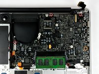
ケースを閉じたまま、Unibodyを裏返しにして水平に置きます。
-
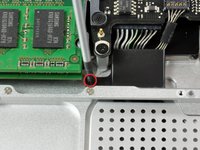
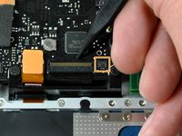
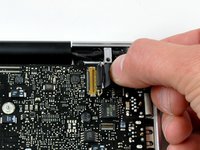
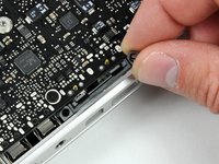
アクセスドアのリリース用ラッチの溝側を押し込んで、出てきた先端をつかみます。 リリース用ラッチが垂直になるまで持ち上げます。
-
-


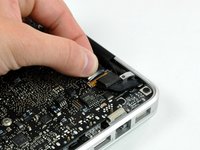


もう少しです!
デバイスを再組立する際は、これらのインストラクションを逆の順番に従って作業を進めてください。
終わりに
デバイスを再組立する際は、これらのインストラクションを逆の順番に従って作業を進めてください。
12 の人々がこのガイドを完成させました。
以下の翻訳者の皆さんにお礼を申し上げます:
en jp
100%

これらの翻訳者の方々は世界を修理する私たちのサポートをしてくれています。 あなたも貢献してみませんか?
翻訳を始める ›
