メインコンテンツにスキップ

このバージョンは誤った内容を含んでいる可能性があります。最新の承認済みスナップショットに切り替えてください。

アーカイブされたガイド
このガイドは将来的な使用のためにのみ保存されてます。ご自身の修理作業には更新バージョンをご利用ください。

必要な工具と部品

  1. , 底ケース: 手順 1、 1の画像 1
    • MacBook Proの底ケースに固定されているP5ペンタローブネジを取り外します。

    • 3.0 mmー8本

    • 2.3 mmー2本

  2. : 手順 2、 1の画像 1
    • クラッチカバー付近の端を持ち上げて、MacBook Proの底ケースを外します。

    • 底ケースを脇に置きます。

  3. , バッテリーコネクタ: 手順 3、 1の画像 1
    • バッテリーコネクタを覆っている注意書きラベルを剥がします。

  4. : 手順 4、 2の画像 1 : 手順 4、 2の画像 2
    • スパッジャーの平面側先端を使って、バッテリーコネクターの接続部分を基板上のソケットから真っ直ぐ引き上げます。

    • バッテリーケーブルを後ろ側に折り曲げ、バッテリーコネクタがアクシデントで基板に接触しないように確認してください。

  5. , AirPort/カメラケーブル: 手順 5、 1の画像 1
    • ピンセットを使って、3本のAirPortアンテナケーブルをAirPortボード上のソケットを持ち上げて接続を外します。

    • ケーブルの接続部分はデリケートです。ソケットやケーブル上をこじ開けるのではなく、コネクタのみ持ち上げてください。

    • 再接続をする際は、コネクタの位置をソケット上に慎重に揃えてください。スパッジャーの平面側を使って、しっかりと押さえて装着します。

  6. : 手順 6、 1の画像 1
    • スパッジャーの先端を使って、カメラケーブルのプラグをファン側に押して、基板上のソケットから外します。

    • 画像のプラグには接点が6つありますが、モデルによっては接点が12個ある場合があります。どちらのソケットでも取り外す方法は同じです。

    • カメラケーブルのプラグが外しにくいと感じた場合は、ファンを覆っているカバーをめくってケーブルを扱い安くしてから、スパッジャーでプラグをソケットから外す方向に慎重に押しながらケーブルを慎重に引っ張って下さい。

    • 基板に対して平行に押してください。コネクタの一方をまず押してから、反対側を押して、ゆっくりと「歩く」ようにプラグをソケットから外してください。こじって持ち上げるとソケットを破損する恐れがあります。

  7. : 手順 7、 3の画像 1 : 手順 7、 3の画像 2 : 手順 7、 3の画像 3
    • 右側ファン上にあるゴム製ヒートシンクカバーの下にスパッジャーの平面側先端を差し込みます。

    • スパッジャーをカバー全体にスライドしながら、接着剤を剥がします。

    • カバーを持ち上げて、裏返します。これで下にあるケーブルにアクセスできます。

  8. : 手順 8、 3の画像 1 : 手順 8、 3の画像 2 : 手順 8、 3の画像 3
    • 指先を使って、AirPort/カメラケーブルをファンから引っ張ります。

    • ケーブルはファンに接着剤で固定されています。そのためダメージを与えないように、引っ張る際はゆっくりと丁寧に作業を進めてください。

    • 丁寧にプラスチックのケーブルガイドからケーブルを外します。

  9. , I/O ボードケーブル: 手順 9、 3の画像 1 , I/O ボードケーブル: 手順 9、 3の画像 2 , I/O ボードケーブル: 手順 9、 3の画像 3
    • I/Oボードケーブルのコネクタが、パッドに切り欠きがある場合、ケーブルを取り外すには、切り欠きの下にあるロックレバーを解除する必要があります。この場合、レバーのラッチが外れるまでコネクタをこじ開けないでください。

    • スパッジャーの平面側先端を使用して、I/Oボードコネクタをロジックボード上のソケットからまっすぐ上にこじ開けます。

    • 再組み立ての際には、ケーブルがたわまないように、この先端を先に接続してください。

    • 同様に、I/OボードのケーブルコネクターをI/Oボードのソケットから外します。

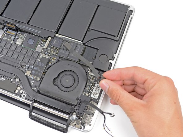
    • MacBook ProからI/Oボードケーブルを外します。

  10. , Airportカード: 手順 10、 1の画像 1
    • ロジックボード上のAirPortカードに固定された2.9 mm T5トルクスネジを1本外します。

  11. : 手順 11、 2の画像 1 : 手順 11、 2の画像 2
    • AirPortカードの両側を摘み、浅い角度(5~10˚)で持ち上げて、ロジックボードに付着している接着剤から乖離します。

    • Air Portカードをロジックボード上のコネクタから水平に引き抜いて取り外します。

  12. : 手順 12、 2の画像 1 : 手順 12、 2の画像 2
    • スパッジャーの先端を使って、右側ファンのリボンケーブルの ZIFソケット 上の固定フラップを持ち上げて裏返します。

    • 固定フラップのヒンジ部分をこじ開けてください。ソケット自体には接触しないでください。

    • 右側ファンケーブルの下に差し込んだプラスチック製の開口ツールをケーブル上部からスライドして、ロジックボードから解放します。

    • ケーブルを外す際はご注意ください。ロジックボードに多量の接着剤で固定されています。

  13. : 手順 13、 1の画像 1
    • ロジックボードに右側ファンを固定している次のネジを外します。

    • 4.4 mm T5トルクスネジー1本

    • 3.9 mm T5トルクスネジー1本

    • 5.0 mm T5トルクスネジ(2 mmカラー)ー1本

  14. : 手順 14、 1の画像 1
    • MacBook Proから右側ファンを持ち上げて取り出します。

    • ファンを再装着する際は、3本のファン用ネジを装着した後にファンリボンケーブルを接続するよりも、先にファンを固定してからケーブルを接続する方が簡単です。

  15. , 左側ファン: 手順 15、 1の画像 1
    • スパッジャーの平面側先端を使って、左側ファンからゴム製ヒートシンクのカバーを持ち上げます。

  16. : 手順 16、 1の画像 1
    • 左側ファンを基板に固定している次のネジを外します。

    • 4.4 mm T5トルクスネジー1本(2mmカラー)

    • 5.0 mm T5トルクスネジー1本(2mmカラー)

    • 3.9 mm T5ワイドヘッドトルクスネジー1本

    • ファンとそのネジを再装着するとき、最初にすべてのネジを緩く取り付けてから、ネジを完全に締め付けないようにしてください。 ファンが少し動いて、ネジをネジ山に挿入するときに適切な位置になるようにするためです。

  17. : 手順 17、 3の画像 1 : 手順 17、 3の画像 2 : 手順 17、 3の画像 3
    • スパッジャーの先端を使って、左側リボンケーブルのZIFソケット上の固定フラップを持ち上げます。

    • 蝶番の固定フラップを持ち上げてください。ソケット自体には接触しないでください。

    • プラスチック製の開口ツールを差し込んだケーブルの上部から左側ファンケーブルの下までスライドして、基板から解放します。

    • ケーブルを外す際はご注意ください。ケーブルは頑丈な接着剤によって基板に固定されています。必要に応じてiOpenerやドライヤーを使ってケーブルに留められた接着剤を柔らかくするため、ケーブルを温めてください。取り外す作業がスムーズにいきます。

    • デバイスから左側ファンを持ち上げて取り出します。

    • ファンを再装着する際は、ファンのネジを3本取り付けた後に行うよりも、ファンを固定の場所に置いてファン用のリボンケーブルを接続する方法がより簡単です。

  18. , SSD: 手順 18、 1の画像 1
    • 基板にSSDを固定している3.1 mm T5トルクスネジを1本外します。

  19. : 手順 19、 2の画像 1 : 手順 19、 2の画像 2
    • ゆっくりと一番右側のSSDを持ち上げて、基板上のソケットから真っ直ぐスライドして外します。

  20. , I/O ボード: 手順 20、 2の画像 1 , I/O ボード: 手順 20、 2の画像 2
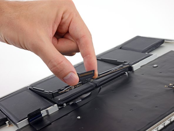
    • スパッジャーの先端を使ってI/Oボードのデータケーブルのロックを持ち上げて外し、バッテリー側に回します。

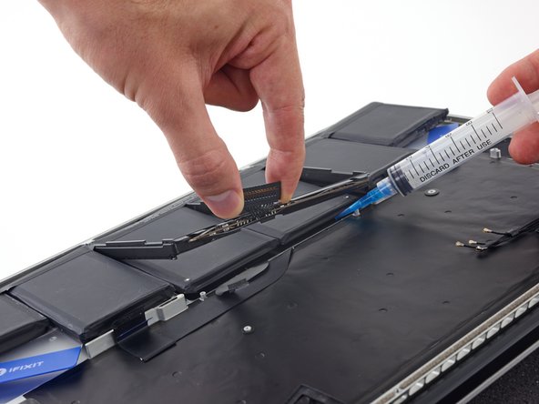
    • スパッジャーの平面側先端を使って、I/Oボードデータのケーブルをまっすぐ基板上のソケットからスライドして外します。

    • ソケットは大変デリケートのため、I/Oボードのデータケーブルを上向きに引っ張らないでください。基板に平行してケーブルを引っ張ります。

  21. : 手順 21、 3の画像 1 : 手順 21、 3の画像 2 : 手順 21、 3の画像 3
    • 基板にI/Oボードを固定している3.1 mm T5トルクスネジを2本外します。

    • モデルによっては、 また、ヒートシンクからシルバーの3.5mmT5トルクスネジを取り外すと、I/Oボードの取り外しが楽になります。

    • ゆっくりとI/Oボードを持ち上げて底ケースから取り出します。

  22. , ロジックボードアセンブリ: 手順 22、 1の画像 1
    • スパッジャーの平面側先端を使って、ロジックボード上のソケットからヘッドホンジャックのコネクターを持ち上げて、接続を外します。

  23. : 手順 23、 2の画像 1 : 手順 23、 2の画像 2
    • スパッジャーの平面側先端を使って、左側スピーカーのコネクターをロジックボード上のソケットから持ち上げて接続を外します。

    • スパッジャーの先端を使って、右側スピーカーのコネクタをロジックボード上のソケットから持ち上げて接続を外します。

    • ケーブルヘッドを持ち上げてください。ソケット自体には接触しないでください。ソケットを持ち上げてしまうと、ロジックボードから外れてしまう恐れがあります。

  24. : 手順 24、 1の画像 1
    • キーボードのリボンケーブルコネクタを覆っているテープがあれば剥がします。

  25. : 手順 25、 3の画像 1 : 手順 25、 3の画像 2 : 手順 25、 3の画像 3
    • スパッジャーの平面側先端を使って、キーボードリボンケーブルのZIFソケット上の固定フラップを持ち上げます。

    • ソケット自体ではなく、ヒンジのついた固定フラップの下をこじ開けてください。ソケットに接触すると、ボードを破損する場合があります。

    • スパッジャーの平面側先端を使って、キーボードリボンケーブルの片側をまずソケットから押し出して、反対側も押し出します。

  26. : 手順 26、 1の画像 1
    • スパッジャーの平面側先端を使って、ロジックボード上のソケットからトラックパッドのリボンケーブルのコネクターを引き上げて外します。

  27. : 手順 27、 1の画像 1
    • ロジックボード上のソケットからキーボードのバックライトコネクターを持ち上げて接続を外します。

  28. : 手順 28、 1の画像 1
    • スパッジャーの先端や指の爪を使ってマイクリボンケーブルのZIFソケット上の固定フラップを引き上げて、接続を外します。

    • 蝶番の固定フラップを引き上げてください。ソケット自体には接触しないでください。

    • マイクリボンケーブルをソケットから外します。

  29. : 手順 29、 2の画像 1 : 手順 29、 2の画像 2
    • スパッジャーの先端を使って、ディスプレイデータケーブルのロックを引き上げて、デバイスのDC-In側に向けて回します。

    • ディスプレイのデーターケーブルをロジックボード上のソケットからまっすぐ引き上げます。

    • ソケットはとても壊れやすい為、ディスプレイデーターケーブルを引き上げないでください。ケーブルをロジックボードと平行に引っ張ります。

  30. : 手順 30、 1の画像 1
    • スパッジャーの平面側先端を使って、MagSafe 2コネクタ付近の盛り上がったネジ頭上のゴム製のネジキャップを丁寧に外します。

  31. : 手順 31、 1の画像 1
    • 上部ケースにロジックボードを固定している次の6本のネジを外します。

    • 2.6 mm T5トルクスネジー1本

    • 5.8 mm T5トルクスネジー2本

    • 3.8 mm T5トルクスネジー1本

    • 5.2 mmナベ頭組込T5トルクスネジー1本

    • 3.5 mm シルバーT5トルクスネジー1本

  32. : 手順 32、 3の画像 1 : 手順 32、 3の画像 2 : 手順 32、 3の画像 3
    • バッテリーに一番近い側から本体デバイスの上部に向けてロジックボードを持ち上げます。

    • スパッジャーの平面側先端を使って、MagSafe 2コネクタをロジックボード下側上のソケットからゆっくりと押して外します。

    • ロジックボードを再装着する際は、赤の印でマークされたケーブルの位置を確認してください。ロジックボードときちんと接続されているか確認します。

    • 上から時計回りに:キーボード、トラックパッド、右側スピーカー、キーボードバックライト、ディスプレイ、マイク、ヘッドフォンジャック、左側スピーカー

  33. : 手順 33、 1の画像 1
    • MacBook Proからロジックボードアセンブリを取り出します。

  34. , スピーカー: 手順 34、 2の画像 1 , スピーカー: 手順 34、 2の画像 2
    • 上部ケースと左側スピーカーを固定している次の3本のネジを外します。

    • 5.6 mm T5 トルクスネジー1本

    • 6.9 mm T5トルクスネジー1本

    • 2.6 mm T5トルクスネジー1本

    • 上部ケースから左側スピーカーを持ち上げて、側に寄せておきます。

    • スピーカーはケースに接着剤で軽く固定されています。

  35. : 手順 35、 2の画像 1 : 手順 35、 2の画像 2
    • 上部ケースと右側スピーカーを固定している次の3本のネジを外します。

    • 5.6 mm T5 トルクスネジー1本

    • 6.9 mm T5トルクスネジー1本

    • 2.6 mm T5トルクスネジー1本

    • MacBook Proから右側スピーカーを取り出します。

    • スピーカーはケースに接着剤で軽く固定されています。

  36. この手順は未翻訳です。 翻訳を手伝う。

    : 手順 36、 1の画像 1
    • Remove the two 3.9 mm T5 Torx screws securing the battery board.

  37. この手順は未翻訳です。 翻訳を手伝う。

    : 手順 37、 1の画像 1
    • The liquid adhesive remover provided in your kit can affect the antireflective coating on your MacBook Pro's display.

    • To protect your display, place a sheet of aluminum foil between the display and keyboard and leave it there while you work.

  38. この手順は未翻訳です。 翻訳を手伝う。

    : 手順 38、 2の画像 1 : 手順 38、 2の画像 2
    • With the front edge of the MacBook Pro facing you, lift the right side and prop it up at a slight angle, using a sturdy foam block or book.

    • In the following steps, you'll apply liquid adhesive remover to the right (outer) edge of the battery. Keeping this side of the MacBook Pro elevated will help the adhesive remover flow underneath the battery.

  39. この手順は未翻訳です。 翻訳を手伝う。

    : 手順 39、 2の画像 1 : 手順 39、 2の画像 2
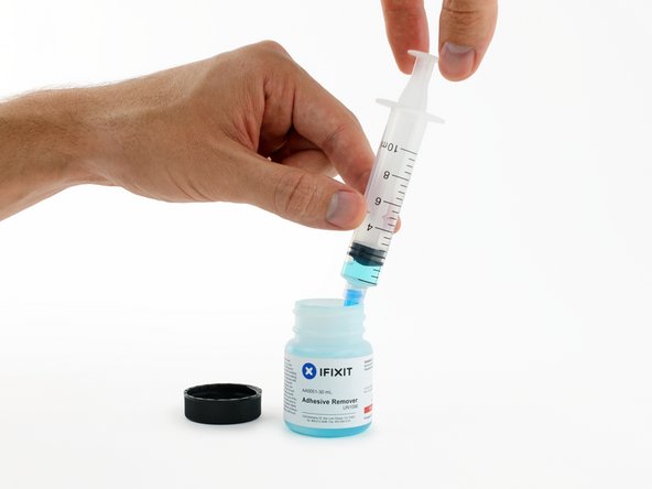
    • Now that your MacBook Pro is fully prepped, it's time to prep yourself.

    • iFixit adhesive remover contains acetone, a mild skin and eye irritant.

    • Wear eye protection when handling and applying the adhesive remover. (Eye protection is included in your kit.)

    • Do not wear contact lenses without eye protection.

    • Protective gloves are also included in your kit. If you are concerned about possible skin irritation, put your gloves on now.

  40. この手順は未翻訳です。 翻訳を手伝う。

    : 手順 40、 2の画像 1 : 手順 40、 2の画像 2
    • Open your container of adhesive remover.

    • Fill the syringe included in your kit with a small amount (approximately 1-2 milliliters) of adhesive remover.

    • It's best to fill the syringe with no more than about 1-2 milliliters of adhesive remover at a time, so as to avoid accidentally applying too much.

    • Refill your syringe as needed throughout the rest of this procedure.

  41. この手順は未翻訳です。 翻訳を手伝う。

    : 手順 41、 2の画像 1 : 手順 41、 2の画像 2
    • Apply a small amount of adhesive remover (approximately 1 ml) evenly along the elevated edge of the outer right battery cell.

    • Wait 2-3 minutes for the liquid adhesive remover to penetrate underneath the battery cell before you proceed to the next step.

  42. この手順は未翻訳です。 翻訳を手伝う。

    : 手順 42、 3の画像 1 : 手順 42、 3の画像 2 : 手順 42、 3の画像 3
    この手順で使用する道具:
    Plastic Cards
    $2.99
    購入する
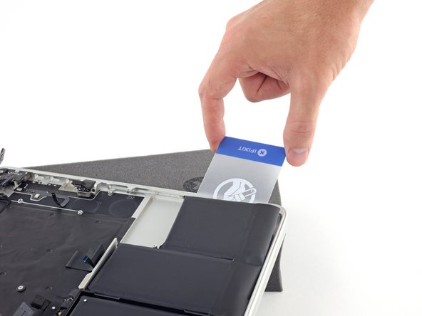
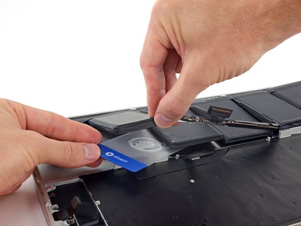
    • Slide one corner of a plastic card under the outer edge of the battery cell.

    • It may help to gently twist the card to open up a slight gap between the battery cell and the MacBook Pro's case.

    • Slide the card farther underneath the battery cell to separate it from the adhesive securing it to the MacBook Pro's upper case.

  43. この手順は未翻訳です。 翻訳を手伝う。

    : 手順 43、 2の画像 1 : 手順 43、 2の画像 2
    • Lift the battery cell to separate it from the MacBook Pro's upper case, but don't try to remove it.

    • Leave the plastic card underneath the battery cell to prevent it from re-adhering as you proceed to the next step.

  44. この手順は未翻訳です。 翻訳を手伝う。

    : 手順 44、 3の画像 1 : 手順 44、 3の画像 2 : 手順 44、 3の画像 3
    • Apply a small amount of adhesive remover (approximately 1 ml) evenly along the elevated edge of the next battery cell.

    • Wait 2-3 minutes for the liquid adhesive remover to penetrate underneath the battery cell before you proceed to the next step.

  45. この手順は未翻訳です。 翻訳を手伝う。

    : 手順 45、 3の画像 1 : 手順 45、 3の画像 2 : 手順 45、 3の画像 3
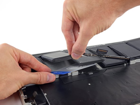
    • Slide one corner of your plastic card underneath the second battery cell.

    • Push the card underneath the second battery cell, and slide it side to side to separate the adhesive underneath.

    • Leave the plastic card underneath both battery cells (or flip them over) to prevent them from re-adhering as you proceed to the next step.

  46. この手順は未翻訳です。 翻訳を手伝う。

    : 手順 46、 3の画像 1 : 手順 46、 3の画像 2 : 手順 46、 3の画像 3
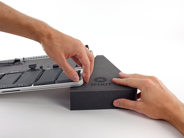
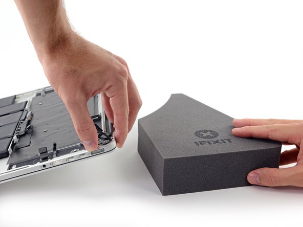
    • It's time to switch sides. Remove your book or foam block and place it under the opposite side of your MacBook Pro.

    • Repeat the procedure from the prior steps to separate the two battery cells on this side:

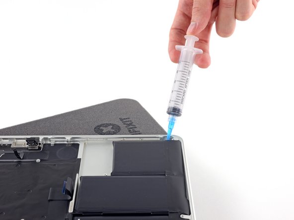
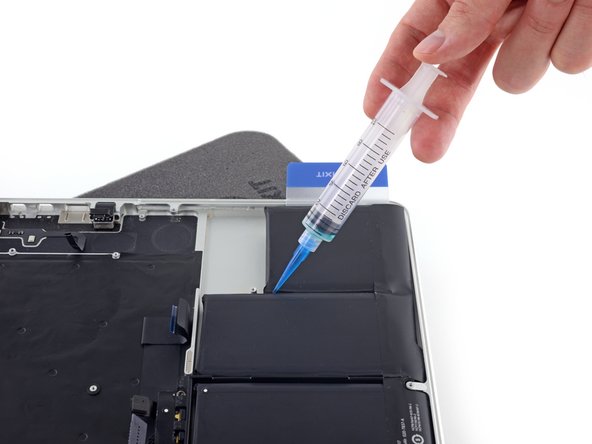
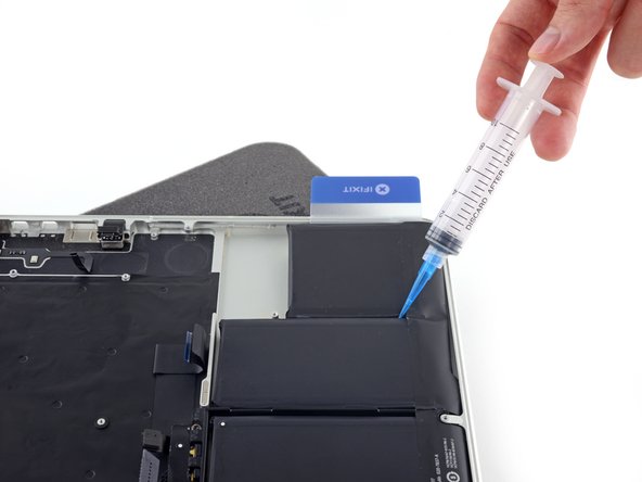
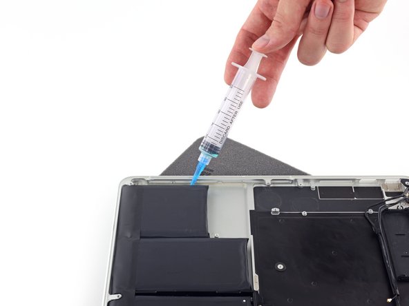
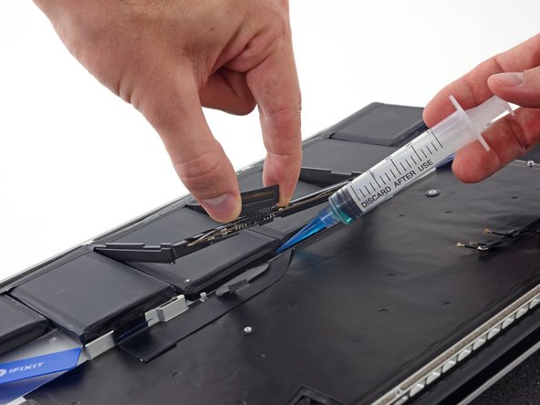
    • Apply your adhesive remover to the elevated edge of the outer battery cell, and wait 2-3 minutes for it to penetrate.

    • Work one corner of a plastic card underneath the battery cell, and slide the card fully underneath the battery cell to separate it.

    • Do the same for the adjacent cell.

    • Leave your plastic card in place or flip the battery cells over to prevent them from re-adhering during the following steps.

  47. この手順は未翻訳です。 翻訳を手伝う。

    : 手順 47、 2の画像 1 : 手順 47、 2の画像 2
    • Remove your book or foam block and place it under the rear edge of your MacBook Pro, near the display hinges.

  48. この手順は未翻訳です。 翻訳を手伝う。

    : 手順 48、 2の画像 1 : 手順 48、 2の画像 2
    • Grab the battery connector or the top edge of the plastic battery frame and lift it slightly, exposing the top edge of the two center battery cells.

  49. この手順は未翻訳です。 翻訳を手伝う。

    : 手順 49、 3の画像 1 : 手順 49、 3の画像 2 : 手順 49、 3の画像 3
    • While lifting the plastic battery frame out of the way, apply a small amount (about 1-2 ml) of adhesive remover underneath the top edge of the two remaining battery cells.

    • Wait 2-3 minutes for the adhesive remover to penetrate before you continue.

  50. この手順は未翻訳です。 翻訳を手伝う。

    : 手順 50、 3の画像 1 : 手順 50、 3の画像 2 : 手順 50、 3の画像 3
    • While lifting the plastic frame out of the way, push one corner of your plastic card underneath the outside edge of the first center battery cell.

    • Do not pry along the edge nearest the battery connector, or you risk damaging the keyboard ribbon cable.

    • Slide your card all the way under the battery cell, and leave it to prevent the battery cell from re-adhering.

  51. この手順は未翻訳です。 翻訳を手伝う。

    : 手順 51、 3の画像 1 : 手順 51、 3の画像 2 : 手順 51、 3の画像 3
    • Repeat the above procedure to separate the last remaining battery cell from the MacBook Pro's upper case.

  52. この手順は未翻訳です。 翻訳を手伝う。

    : 手順 52、 2の画像 1 : 手順 52、 2の画像 2
    • Lift the battery with the plastic frame and slide it back toward the MacBook Pro’s hinge until it clears the screw posts holding it to the upper case.

  53. この手順は未翻訳です。 翻訳を手伝う。

    : 手順 53、 2の画像 1 : 手順 53、 2の画像 2
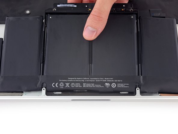
    • Lift and remove the battery.

    • Before installing your new battery, remove all the old adhesive from the MacBook Pro's case.

    • With a little luck, you can slowly pull out each strip of adhesive with your fingers.

    • Otherwise, soak each strip of adhesive with a bit of adhesive remover for 2-3 minutes, and then scrape it out with a plastic tool. This can take quite a bit of work, so be patient.

    • Mop up any remaining adhesive remover and give your MacBook Pro a few minutes to air dry.

    • The replacement battery included in your iFixit kit comes with adhesive pre-installed. Test the battery's fit and alignment carefully before peeling off the film covering the adhesive, and then press each cell firmly into place. If any additional films/liners are present that weren't on your original battery, remove them now.

    • Calibrate your battery before using it: allow it to drain overnight, then charge it to 100% and drain it again until your MacBook Pro shuts down automatically. Charge it again and use it normally.

    • If you notice any unusual behavior or problems after installing your new battery, you may need to reset your MacBook Pro's SMC.

ゴール

2 の人々がこのガイドを完成させました。

作成者

2人の作成者と共同で作成されました。

Jeff Suovanen

メンバー登録日: 08/06/13

427,925 ポイント

259のガイドは作成済み

チーム

iFixit iFixit人のメンバー

Staff

135 メンバー

16,757のガイドは作成済み

2 件のコメント

Thank you! Really good, easy to follow instructions with good informative pictures.

bigfatbassdrum - 返信

Why does this guide insist on removing the logic board when it does not block removal of the battery? It’s not necessary to add those 30-40 steps to this process: this replacement can be done without taking out the logic board and all of the various risky wire pulls that it requires.

Ben Doherty - 返信

コメントを追加

統計データ:

過去 24時間: 0

過去 7 日: 2

過去 30 日: 5

今までの合計 772