メインコンテンツにスキップ

このバージョンは誤った内容を含んでいる可能性があります。最新の承認済みスナップショットに切り替えてください。

必要な工具と部品

  1. , バッテリー: 手順 1、 3の画像 1 , バッテリー: 手順 1、 3の画像 2 , バッテリー: 手順 1、 3の画像 3
    • 指を使ってバッテリー固定ラッチを2つともバッテリーから離れる方向に押してから、バッテリーを持ち上げて本体から取り外します。

  2. , メモリパネル: 手順 2、 2の画像 1 , メモリパネル: 手順 2、 2の画像 2
    • メモリパネルから全て同じ長さ2mmのプラスネジを外します。

    • メモリパネルをつかめるように持ち上げてから手前にずらして、筐体から引っ張って外します。

  3. , 上側筐体: 手順 3、 1の画像 1
    • 長さ2.8mmのプラスネジ2本を外します。ネジはバッテリー収納スペース内のバッテリー固定ラッチの近くにあります。

  4. : 手順 4、 1の画像 1
    • 以下の合計6本のネジを外します。

    • 長さ10mmのT6トルクスネジがメモリスロットの両端にあります。

    • 長さ14.5mmのプラスネジがヒンジ沿いにあります。

  5. : 手順 5、 1の画像 1
    • 本体のポート側の側面にある、長さ3.2mmのプラスネジ4本を外します。

  6. : 手順 6、 1の画像 1
    • 本体を反時計回りに90度回して、本体の背面にある長さ3.2mmのプラスネジ2本を外します。

  7. : 手順 7、 1の画像 1
    • 本体をさらに反時計回りに90度回して、本体側面にある長さ3.2mmのプラスネジ4本を外します。

  8. : 手順 8、 3の画像 1 : 手順 8、 3の画像 2 : 手順 8、 3の画像 3
    • 上側筐体を急に引っ張り上げないでください。上側筐体はリボンケーブルでロジックボードに接続されています。

    • 上側筐体のヒンジ側を持ち上げてから側面に指を当てて、順番にケースの固定を外して下さい。側面の固定を外し終わった後、手前側の固定を外すために上側筐体を上下に揺する必要があるかも知れません。

    • DVD挿入口の上には4つの樹脂製の爪があり、また赤外線レシーバーの上と左側にも爪があります。これらの爪をこじらずに外すのは大変に難しいです。また、組み付け直すのも難しくなっています。

    • 組み立て直す際の注意: 爪がスロットに嵌る時のカチッという音が聞こえるまで、それぞれの爪がある場所の真上にある上側筐体の端をしっかり押し下げて下さい。

    • 組み立て直す際の注意: DVD挿入口の上の中央2つの爪は対策なしで正しく嵌ることはほとんどなく、単純に筐体をまっすぐ押し下げると爪が嵌る代わりにDVD挿入口を変形させてしまう恐れがあります。樹脂製のスパッジャーなどをDVD挿入口の爪の真下部分ににぴったり合うように差し込んで支えてから、カチッという音が聞こえるまで上側筐体を押し下げて下さい。

  9. : 手順 9、 2の画像 1 : 手順 9、 2の画像 2
    • トラックパッドとキーボードのリボンケーブルとロジックボードの接続を外します。必要であればカプトンテープを剥がして下さい。

    • 注意:キーボードを筐体から外さずにハードディスクを交換することもできますが、ハードディスクの交換作業で両手を使うためには、何らかの方法でキーボードを持ち上げたまま固定しておく必要があります。

    • トラックパッドとキーボードのリボンケーブルを取り外す際は、上側筐体の奥側がヒンジ付近から外れていることを確認して下さい。キーボード両脇のネジ取り付け部分を、アクシデントで変形してしまうことがあります。

    • これで上側筐体が外せるようになりました。

  10. この手順は未翻訳です。 翻訳を手伝う。

    : 手順 10、 1の画像 1
    • Disconnect the two or three antenna cables attached to the Airport Extreme card. Depending on your model, one of the three cables may be unused and capped with a black shrink tube.

    • Apple was kind enough to include a label showing where each color antenna cable plugs in - just make sure to look at this when reconnecting the antenna cables.

  11. この手順は未翻訳です。 翻訳を手伝う。

    : 手順 11、 1の画像 1
    • Deroute the Airport antenna cables from their channel in the left speaker.

  12. この手順は未翻訳です。 翻訳を手伝う。

    : 手順 12、 1の画像 1
    • Disconnect the iSight cable from the logic board by sliding the cable to the left and out of its connector.

  13. この手順は未翻訳です。 翻訳を手伝う。

    : 手順 13、 1の画像 1
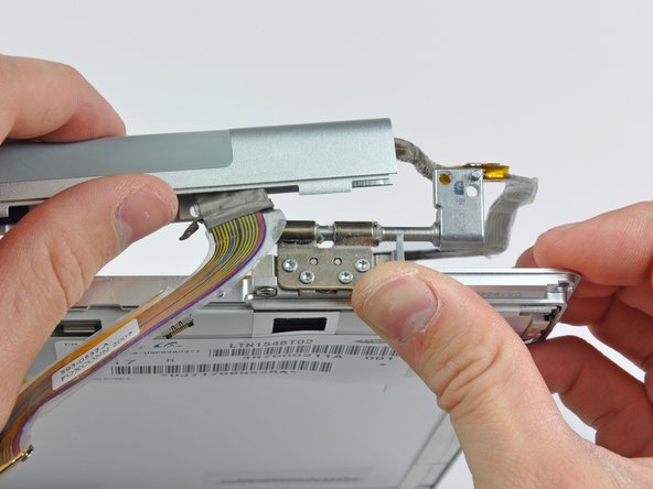
    • Support the display with one hand while removing the following screws:

    • One 9.5 mm silver T6 Torx screw with threads on only 3 mm of the shaft on the inside of the display hinges.

    • One 9.5 mm silver T6 Torx screw with threads on the entire shaft on the outside of the left hinge.

    • One 9.2 mm full thread T6 Torx screw securing the iSight cable ground loop to the fan.

  14. この手順は未翻訳です。 翻訳を手伝う。

    : 手順 14、 1の画像 1
    • Disconnect the inverter cable from the left I/O board by placing a spudger beneath the cable and lifting up.

  15. この手順は未翻訳です。 翻訳を手伝う。

    : 手順 15、 2の画像 1 : 手順 15、 2の画像 2
    • Disconnect the display data cable from the logic board.

    • Remove the foam bumper from the top of the right hinge of the display.

  16. この手順は未翻訳です。 翻訳を手伝う。

    : 手順 16、 1の画像 1
    • Remove the silver 9.2 mm T6 Torx securing the ground loop in the display data cable to the casing.

  17. この手順は未翻訳です。 翻訳を手伝う。

    : 手順 17、 1の画像 1
    • Support the display with one hand while removing the following screw:

    • One 9.5 mm silver T6 Torx screw with threads on only 3 mm of the shaft on the inside of the display hinges.

  18. この手順は未翻訳です。 翻訳を手伝う。

    : 手順 18、 1の画像 1
    • Grasp the display assembly on both sides and lift it up and out of the computer.

  19. この手順は未翻訳です。 翻訳を手伝う。

    : 手順 19、 2の画像 1 : 手順 19、 2の画像 2
    • Remove the 4.5 mm Phillips screws from the lower left and right corners of the display (two screws total). These screws have a .8 mm thick head.

  20. この手順は未翻訳です。 翻訳を手伝う。

    : 手順 20、 3の画像 1 : 手順 20、 3の画像 2 : 手順 20、 3の画像 3
    • Insert the flat end of a spudger perpendicular to the face of the display between the plastic strip attached to the rear bezel and the front bezel.

    • Do not insert your spudger between the plastic strip and the rear bezel.

    • With the spudger still inserted, rotate it away from the display to separate the front and rear bezels.

    • Work along the right edge of the display until the rear bezel is evenly separated from the front bezel.

  21. この手順は未翻訳です。 翻訳を手伝う。

    : 手順 21、 2の画像 1 : 手順 21、 2の画像 2
    • Insert your spudger between the front and rear display bezels at the lower right corner of the display.

    • Pry the rear bezel away from the front bezel to slightly separate the bottom edge of the rear display bezel.

  22. この手順は未翻訳です。 翻訳を手伝う。

    : 手順 22、 2の画像 1 : 手順 22、 2の画像 2
    • Insert the flat end of a spudger into the gap between the rear display bezel and the clutch cover.

    • Twist the spudger to separate the lower edge of the rear display bezel from the clutch cover.

    • Work along the lower edge of the rear bezel until it is evenly separated from the clutch cover.

  23. この手順は未翻訳です。 翻訳を手伝う。

    : 手順 23、 3の画像 1 : 手順 23、 3の画像 2 : 手順 23、 3の画像 3
    • Now that the right and bottom edges of the rear bezel are slightly separated from the front bezel, use a spudger to pop the rear bezel off the tabs near the lower right corner of the display.

  24. この手順は未翻訳です。 翻訳を手伝う。

    : 手順 24、 2の画像 1 : 手順 24、 2の画像 2
    • Insert the flat end of a spudger between the front bezel and the plastic strip attached to the rear bezel near the screw holes at the bottom corners of the display.

    • Rotate your spudger toward the rear bezel to separate it from the front bezel.

    • If necessary, continue separating the left edge of the rear bezel off the tabs on the front display bezel.

  25. この手順は未翻訳です。 翻訳を手伝う。

    : 手順 25、 1の画像 1
  26. この手順は未翻訳です。 翻訳を手伝う。

    : 手順 26、 1の画像 1
    • Use the tip of a spudger to lift the LED driver board out of the clutch cover.

  27. この手順は未翻訳です。 翻訳を手伝う。

    : 手順 27、 1の画像 1
    • Disconnect the backlight cable by pulling its connector away from the socket on the LED driver board.

  28. この手順は未翻訳です。 翻訳を手伝う。

    : 手順 28、 1の画像 1
    • Do not put any excessive strain on the LED driver cable ground loop. It is a very thin and delicate wire that is easily broken.

    • Disconnect the LED driver cable by pulling its connector away from the socket on the inverter board.

    • Remove the LED driver board and set it aside.

  29. この手順は未翻訳です。 翻訳を手伝う。

    : 手順 29、 2の画像 1 : 手順 29、 2の画像 2
    • Remove the two pieces of kapton tape covering the display data cable.

    • Remove the strip of tape securing the iSight cable to the LCD.

    • Peel the three antenna straps off the lower edge of the LCD.

  30. この手順は未翻訳です。 翻訳を手伝う。

    : 手順 30、 1の画像 1
    • Disconnect the display data cable by pulling its connector toward the bottom edge of the display, away from the socket on the LCD.

  31. この手順は未翻訳です。 翻訳を手伝う。

    : 手順 31、 1の画像 1
    • Remove the two Phillips screws securing the ground straps for the display data cable and LED driver board cable to the clutch cover.

  32. この手順は未翻訳です。 翻訳を手伝う。

    : 手順 32、 1の画像 1
    • Remove the Phillips screw hidden behind the display data cable.

  33. この手順は未翻訳です。 翻訳を手伝う。

    : 手順 33、 1の画像 1
    • Remove the three Phillips screws behind antenna straps along the bottom edge of the display.

  34. この手順は未翻訳です。 翻訳を手伝う。

    : 手順 34、 1の画像 1
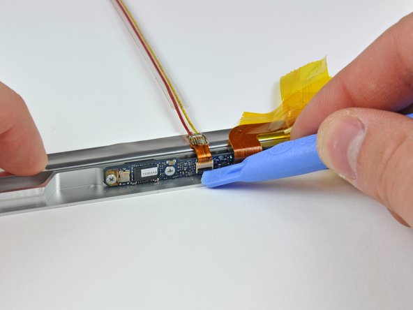
    • To remove the clutch assembly, first insert the flat end of a spudger into the gap between the clutch hinge and the clutch cover where the cables exit.

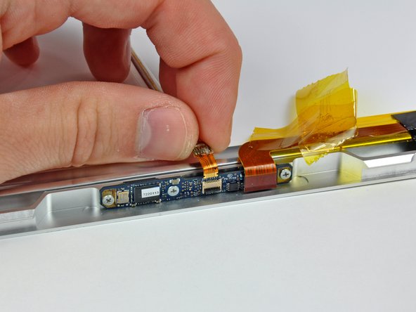
    • While prying the clutch assembly away from the clutch hinge with your spudger, use a plastic opening tool to increase the gap between the clutch cover and the front display bezel.

    • Work your way along the length of the clutch cover to fully separate the adhesive.

  35. この手順は未翻訳です。 翻訳を手伝う。

    : 手順 35、 2の画像 1 : 手順 35、 2の画像 2
    • Push the clutch assembly off each of the clutch hinges and remove it from the display.

  36. この手順は未翻訳です。 翻訳を手伝う。

    : 手順 36、 1の画像 1
    • Peel back the pieces of tape covering the iSight cable.

    • Hold the iSight cable down as you peel back the tape. It is not necessary to completely remove the tape.

  37. この手順は未翻訳です。 翻訳を手伝う。

    : 手順 37、 3の画像 1 : 手順 37、 3の画像 2 : 手順 37、 3の画像 3
    • Use the edge of a plastic opening tool to flip up the ZIF cable lock.

    • Slide the iSight cable out of its socket.

  38. この手順は未翻訳です。 翻訳を手伝う。

    : 手順 38、 1の画像 1
    • Remove the iSight cable from the display.

ゴール

11 の人々がこのガイドを完成させました。

作成者

5人の作成者と共同で作成されました。

Walter Galan

694,773 ポイント

1,203のガイドは作成済み

0 件のコメント

コメントを追加

統計データ:

過去 24時間: 5

過去 7 日: 10

過去 30 日: 17

今までの合計 23,771