このバージョンは誤った内容を含んでいる可能性があります。最新の承認済みスナップショットに切り替えてください。
必要な工具と部品
-
-
この手順は未翻訳です。 翻訳を手伝う。
-
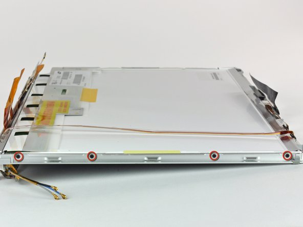
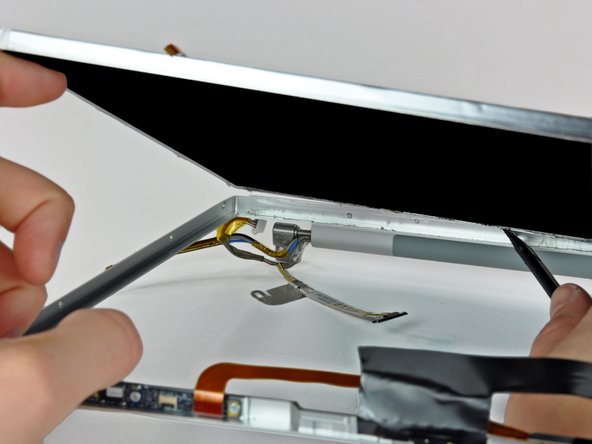
Support the display with one hand while removing the following screws:
-
One 9.5 mm silver T6 Torx screw with threads on only 3 mm of the shaft on the inside of the display hinges.
-
One 9.5 mm silver T6 Torx screw with threads on the entire shaft on the outside of the left hinge.
-
One 9.2 mm full thread T6 Torx screw securing the iSight cable ground loop to the fan.
-
-
この手順は未翻訳です。 翻訳を手伝う。
-
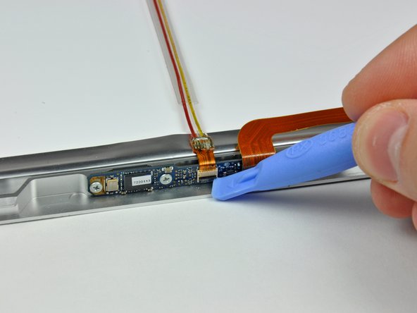
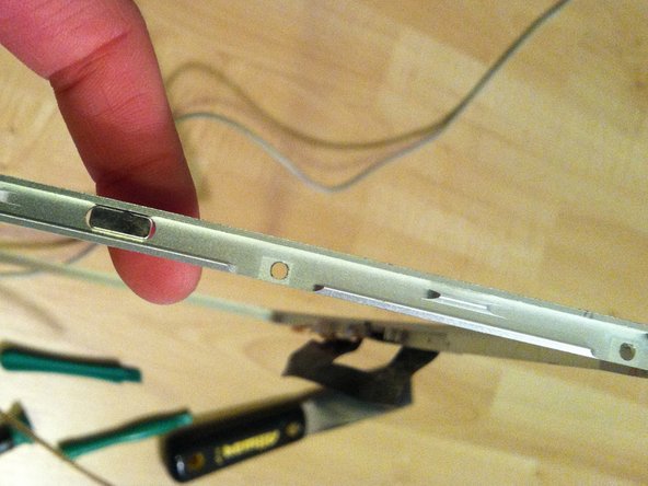
Insert the flat end of a spudger perpendicular to the face of the display between the plastic strip attached to the rear bezel and the front bezel.
-
With the spudger still inserted, rotate it away from the display to separate the front and rear bezels.
-
Work along the right edge of the display until the rear bezel is evenly separated from the front bezel.
-
-
この手順は未翻訳です。 翻訳を手伝う。
-
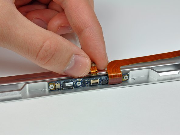
Insert the flat end of a spudger into the gap between the rear display bezel and the clutch cover.
-
Twist the spudger to separate the lower edge of the rear display bezel from the clutch cover.
-
Work along the lower edge of the rear bezel until it is evenly separated from the clutch cover.
-
-
この手順は未翻訳です。 翻訳を手伝う。
-
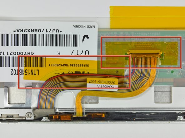
Slightly lift the lower edge of the display and pull it away from the rear display bezel.
-
Go here for the guide to continue replacing the screen: MacBook Pro 15" Core 2 Duo Models A1226 and A1260 LCD Panel Replacement
-
-
この手順は未翻訳です。 翻訳を手伝う。
-
Now that the top edge is free, slightly lift the LCD out of the front bezel for enough room to pry the steel strip along the lower edge of the LCD away from the front bezel.
-
Pry along the lower edge of the LCD until it is freed from the adhesive on the front bezel.
-
Avoid pulling the edge of the LCD unit from the screen. Be sure to insert the tool between the metal of the bezel and the metal of the LCD. If the adhesive is very strong, make a couple trips across the bottom edge to avoid applying too much pressure.
-


139 の人々がこのガイドを完成させました。

7 件のコメント
I didn't have any trouble getting this apart - I used a small screwdriver from a jewelry repair kit (the set of six super small screwdrivers). I slide it in on the left front where it was open and slid it towards the IR thing. After that clip opened up I just slid it over towards the DVD drive... presto. Will update when I put this back together in a couple days. This guide should warn in the beginning to keep the screws identified in some way or you'll have a %*^! of time putting it back together.
I didn't have a spudger handy, but I got by just fine using an old credit card. Don't use a current one, as I dented up the edges pretty good in the process.
I've disassembled many a pc laptop without instructions, but macs are special ;) it was very helpful to have all the details spelled out for me. Thanks!
Be very carefull and bee patience. It´s very helpfull to have something like the ifixit magnetic project mat to keep the screws in order, otherwise you will have a hard time to put the parts together.