メインコンテンツにスキップ

このバージョンは誤った内容を含んでいる可能性があります。最新の承認済みスナップショットに切り替えてください。

必要な工具と部品

  1. この手順は未翻訳です。 翻訳を手伝う。

    : 手順 1、 1の画像 1
    • Use your fingers to push both battery release tabs away from the battery, and lift the battery out of the computer.

  2. : 手順 2、 1の画像 1
    • メモリドアから3つの同一のプラスネジを外します。

  3. この手順は未翻訳です。 翻訳を手伝う。

    : 手順 3、 1の画像 1
    • Lift the memory door up enough to get a grip on it, and slide it toward you, pulling it away from the casing.

  4. , 上部ケース: 手順 4、 1の画像 1
    • ラッチ付近のバッテリーコンパートメントに留められた2.8mmプラスネジを2本外します。

  5. : 手順 5、 1の画像 1
    • 次の6本のネジを外します。

    • RAMスロットの片側にある10mm T6トルクスネジを2本外します。

    • 蝶番沿いにある14.5mmプラスネジを4本外します。

  6. : 手順 6、 1の画像 1
    • コンピュータのポート側に留められた3.2mmプラスネジを4本外します。

  7. : 手順 7、 1の画像 1
    • コンピュータを90度回転させ、コンピュータの裏側から3.2mmプラスネジを2本外します。

  8. : 手順 8、 1の画像 1
    • 再度コンピュータを90度回転させ、コンピュータ側面から3.2mmプラスネジを4本外します。

  9. この手順は未翻訳です。 翻訳を手伝う。

    : 手順 9、 1の画像 1
    • Do not yank the upper case off quickly. The case is attached to the logic board via a ribbon cable.

    • Lift up at the rear of the case and work your fingers along the sides, freeing the case as you go. Once you have freed the sides, you may need to rock the case up and down to free the front of the upper case (there are some hidden plastic clips that need to be clicked off).

  10. : 手順 10、 1の画像 1
    • ロジックボードからトラックパッドとキーボードのリボンケーブルの接続を外し、必要であればテープを剥がします。

    • 上部ケースを取り外します。

  11. この手順は未翻訳です。 翻訳を手伝う。

    : 手順 11、 1の画像 1
    • Disconnect the three antenna cables attached to the Airport Extreme card.

    • Apple was kind enough to include a label showing where each color antenna cable plugs in - just make sure to look at this when reconnecting the antenna cables.

  12. この手順は未翻訳です。 翻訳を手伝う。

    : 手順 12、 1の画像 1
    • Deroute the Airport antenna cables from their channel in the left speaker.

  13. この手順は未翻訳です。 翻訳を手伝う。

    : 手順 13、 1の画像 1
    • Disconnect the iSight cable from the logic board by sliding the cable to the left and out of its connector.

  14. この手順は未翻訳です。 翻訳を手伝う。

    : 手順 14、 1の画像 1
    • Disconnect the inverter cable from the logic board by placing a spudger beneath the cable and lifting up.

  15. この手順は未翻訳です。 翻訳を手伝う。

    : 手順 15、 1の画像 1
    • Disconnect the display data cable from the logic board by pulling sideways.

  16. この手順は未翻訳です。 翻訳を手伝う。

    : 手順 16、 1の画像 1
    • Remove the silver T6 Torx securing the ground loop in the display data cable to the casing.

  17. この手順は未翻訳です。 翻訳を手伝う。

    : 手順 17、 1の画像 1
    • Support the display with one hand while removing the following 3 screws:

    • Two 9.5 mm silver T6 Torx screws with threads on only part of the shaft on the inside of the display hinges.

    • One 9.5 mm silver T6 Torx screw with threads on the entire shaft on the outside of the left hinge.

  18. この手順は未翻訳です。 翻訳を手伝う。

    : 手順 18、 1の画像 1
    • Grasp the display assembly on both sides and lift it up and out of the computer.

  19. この手順は未翻訳です。 翻訳を手伝う。

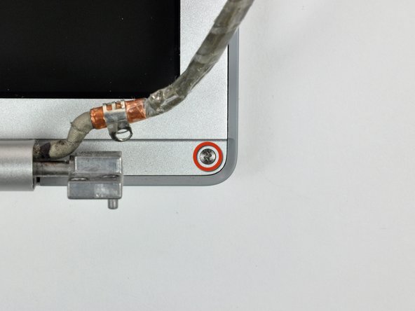
    , リアディスプレイベゼル: 手順 19、 2の画像 1 , リアディスプレイベゼル: 手順 19、 2の画像 2
    • Remove the two 5 mm Phillips screws from the lower left and right corners of the display (two screws total).

  20. この手順は未翻訳です。 翻訳を手伝う。

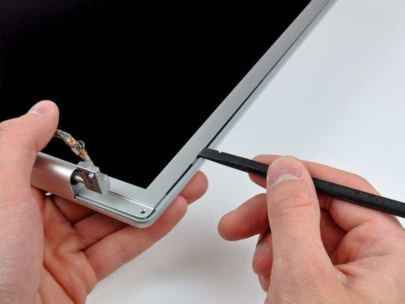
    : 手順 20、 3の画像 1 : 手順 20、 3の画像 2 : 手順 20、 3の画像 3
    • Insert the flat end of a spudger perpendicular to the face of the display between the plastic strip attached to the rear bezel and the front bezel.

    • Do not insert your spudger between the plastic strip and the rear bezel.

    • With the spudger still inserted, rotate it away from the display to separate the front and rear bezels.

    • Work along the left edge of the display until the rear bezel is evenly separated from the front bezel.

  21. この手順は未翻訳です。 翻訳を手伝う。

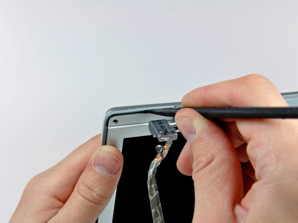
    : 手順 21、 3の画像 1 : 手順 21、 3の画像 2 : 手順 21、 3の画像 3
    • Insert the flat end of a spudger perpendicular to the face of the display between the plastic strip attached to the rear bezel and the front bezel.

    • With the spudger still inserted, rotate it away from the display to separate the front and rear bezels.

    • Work along the right edge of the display until the rear bezel is evenly separated from the front bezel.

  22. この手順は未翻訳です。 翻訳を手伝う。

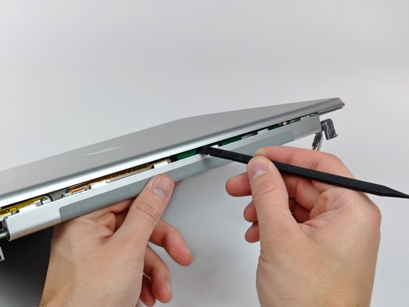
    : 手順 22、 3の画像 1 : 手順 22、 3の画像 2 : 手順 22、 3の画像 3
    • Insert the flat end of a spudger between the front bezel and the plastic strip attached to the rear bezel near the screw holes at the bottom corners of the display.

    • Rotate your spudger toward the rear bezel to separate it from the front bezel.

    • If necessary, enlarge the gap between the lower edge of the rear bezel and the clutch cover until the two components are completely separated.

  23. この手順は未翻訳です。 翻訳を手伝う。

    : 手順 23、 1の画像 1
    • Lift the rear bezel by its bottom edge and rotate it away from the display assembly to separate the top edge.

    • Remove the rear display bezel from the display assembly.

ゴール

5 の人々がこのガイドを完成させました。

作成者

1人の作成者と共同作成されました。

Ben Eisenman

87,681 ポイント

59のガイドは作成済み

0 件のコメント

コメントを追加

統計データ:

過去 24時間: 0

過去 7 日: 4

過去 30 日: 5

今までの合計 8,392