はじめに
このガイドを参考してMacBook Pro 15'' Retina Display Mid 2015のロジックボードを交換してください。
もしヒートシンクを取り外した後、必ず放熱グリスの除去と再塗布をしてください。その際、こちらのガイドを参照してください。
必要な工具と部品
-
-
クラッチカバーに最も近い端から持ち上げて、MacBook Proの底面ケースを持ち上げます。
If you buy the entire kit, make sure you use the opening tool! I cut both of my index fingers trying to slide it off.
Additionally, this is an “opportunity” to clean the cooling fans - and any other obvious dust magnets - with a can of compressed air. On the laptop I worked on, the cooling fans had sufficient dust to not “spin” freely - showing signs of “drag”. After blasting each cooling fan with compressed air (including from the exhaust vent side, as hitting the fins alone wasn’t adequate), they both spin freely now. No obvious signs of battery swelling on mine, but lack of adequate airflow could have been a factor with original battery aging/failure.
Good opportunity to give a good clean out. Air duster and small clean paint brush on plastic surfaces to clean up essential vents and fans. You can load fan monitor and control software to see what your your system is doing and how it improves with a clean up.
-
-
pretty hard to put it back, so I just remove the clips on the upper case....
The trick to putting it back on is to guide your fingers to the same level as the clips, and then when you put the case down move your hand from the left side of the case to the right side of the case; applying pressure when you reach the area where the clips are.
Impossible to put those peds into the upper case clips! It just does not hold there, it fits but just does the ‘click’ sound and goes back. Is it possible to buy those clips as spare part? Thank you for help.
Lopez Loku - 返信
Same for me. It just never clips, regardless of the precision and the amount of force I apply.
I also think I stripped the screws holding the clips in place. Does anyone know what screw characteristics should I look for as a replacement?
Bloated battery had already popped my clips.
-
-
バッテリーコネクタを覆うステッカーを巻き戻します。
You only need to remove the tape to the edge of the flap. This is enough to be able to pry the battery connector up.
+1 to above comment
Note that the photo is taken from the hinge side - the other way to the photo in step 3
I chanced it, didnt disconnect the battery and all is well even after giving the insides a good vacuuming before changing the SSD.
You don’t actually need to remove the tape or even peel it off at all. Just pull up the battery connector up with the tape still attached.
AJ Lorenzo - 返信
pay attention that the macbook in this picture is presented the “wrong side”: if you accidentally remove the tape covering the trackpad cable and thereby also take the trackpad cable out of the zif-socket, your keyboard and trackpad won’t work anymore. putting the trackpad cable back into the (tiny) socket will fix the issue though.
-
-
-
バッテリーコネクターの両側を静かに持ち上げて、コネクターをロジックボード上のソケットから引き出します。
-
バッテリーコネクターが誤ってロジックボードに接触しないように、コネクターをバッテリーの方に戻してください。
@lawrencetaylor On any electronics repair, you need to disconnect all sources of power before you start. It’s a basic safety precaution and also removes the risk of accidentally shorting a connection somewhere (which can potentially kill your MacBook).
I chanced it, didnt disconnect the battery and all is well even after giving the insides a good vacuuming before changing the SSD.
Picture doesn’t match the computer. Hard to tell which connector to disconnect
Hi James, are you sure you have the correct guide for your machine? Try using our MacBook Identification tool.
I used the identification tool and can confirm what James is seeing. The picture doesn’t match for this step. There is no piece with visible holes punched in it.
There is an extra piece of plastic on the connector, you might want to peel that off too. It’s not in the pictures.
Ellie B -
There is a battery cover with two T5 screws that must be removed before prying on the connector.
Hi Dennis,
Thanks for bringing this up! I’ll work on verifying this and adjust the guide as needed.
I need dis board hw much
After separating the battery connector, I took the addd precaution of placing a folded post-it between the connector bank and the socket.
You can also use a plastic tool to hold back the battery connector. My connector was under the plastic tab and had no screws. You may need to check the build version as there are a number of A1398 versions.
When you install the new battery, it may look like the holes in the connector need to be slid on to the connector toward the rear of the mac. I tried bending the cable to make it work. This could damage the cables. You really need only push directly downward on the connector, as you pulled up on it to remove it initially. It will pop into place with a little pressure, just make sure it's lined up properly.
I had to use quite a lot of pressure to make the connector on my new battery pop all the way down. I thought it was down already when it was only half way, as I was afraid to use too much force. Maybe it varies between different battery brands, but just make sure that the connector should go all the way down and not have a gap between the two parts.
If you don't know what the/a logic board is, you probably shouldn't be opening devices.
Art Hackett. Not useful. This guide is for laypeople. Nobody is supposed to know much of anything. That's the point of the guide and the existence of iFixit. You could have used that time to explain what the logic board is for people who are already here anyway.
Anyway onward and upward. If you don't know what a logic board is and you're here. https://www.google.com/search?q=macbook+...
There, now you're an expert like Art. -
-
-
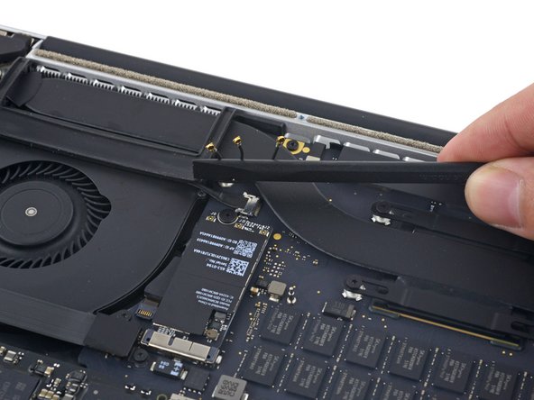
ピンセットもしくはスパッジャーを使って、AirPortボード上のソケットからAirPortアンテナケーブルの3箇所をこじ開けて外し、作業の邪魔にならないように反対側に折り曲げます。
-
再接続の際は、コネクタをソケット上の位置に揃えて、スパッジャーの平面側を使ってしっかりと押さえ込んで装着します。
When reconnecting these tiny wires, use one hand to guide and align the connector by holding the wire and the other hand to press them down with a flat end of a spudger. Spent 10 minutes figuring it out and connecting the first one, then only a few seconds on both of the remaining connectors :)
If you try to do this with one hand, it’s extremely easy to move them out of the alignment while pressing them down.
I think there is a better way - where you disconnect the wifi card using the black screw in middle of wire 2 and 3 first and then untie these connectors. I pryed away the connectors but the sockets on the card were all damaged during the process. Ended up having to get a replacement card before reassembly could be completed. So again there are 2 components - connectors which are being pryed away and really fine and delicate socket. Very easy to damage them. Better to take the card off and delicately peel these connectors off. I would not recommend using these pry sticks mentioned here for that.
ATTENTION ! Cette étape est grandement sous-estimée, aucune mention de la délicatesse de l’opération contrairement à d’autres étapes bien plus facile… De plus, il semble possible de sauter cette étape en déconnectant seulement la carte comme expliquer sur la version anglophone du guide !!! J’ai endommagé le connecteur le plus proche du ventilateur, pour rien… Heureusement, tout semble fonctionner correctement…
AirPort/Camera Cables? not AirPort/Bluetooth Cables?
Agreed with Abhishek - removing the wifi card first makes this much easier.
How do you know which is which when reassembling?
I highly suggest against disconnecting these wires. It's very likely that you will damage either sockets or wires. Do as others recommend, just remove the network card. Prying tool is not good for this step. I broke 1 out of 3 sockets. I wish I read all the comments before operating. Now I gotta get another card :(
what size driver does this require? My pentalobe doesnt seem to be the right size.
As many have mentioned, don’t disconnect the wires is reallly a pain in the a… to connect them, it wont be easy and will take a lot of patience….. Better disconnect the card and carefully leave the wires connected.
Just finished replacing both speakers using this guide. VERY good. I did not remove the individual wires - just removed the card with wires attached. Seemed to be the safer, easier way to go.
How? can you explain the procedure?
I’m attempting taking the card out but leaving the wires attached as mentioned. A Torx T5 worked for me on that screw. I then very slightly lifted up the end of the card where the wires are attached and pulled it straight out of the slot on the opposite side.
Just finished replacing my display LVDS Cable with this guide and another one; awesome. I as well just removed the card and left the wires attached. Much easier.
This is one of those skills that you get experience right after you need it.
I learned these connectors doing RF work. They require a deft touch. Put slight downward pressure while you work to align the pair. Once you get the hang of it, you will know when they are aligned, and they will go back together with a light push and make a slight snap.
If they don’t immediately pop together with a light push, they’re not aligned quite right. Don’t force them, they have a very limited number of make/break cycles.
The cables should retain their bent shape well enough to show where each goes. One it too short to go too far off, and one is too long to fit to the nearest connection.
I did not bother with the danger of removing cables or cards or logic board. I spent 30 mins removing my battery carefully, using string and CT1 multisolve which isn’t dangerous to plastic.
i slid my string under the battery and see-saw underneath and sprayed Ct1 Multisolve underneath. I’ve now done both my macbooks. Didn’t destroy any cables or risk it. I put a few paper sheets over my logic board to cover any spray back. Simple see-saw and a palstic card, the blue spludger and the black long spluger.
Yes, I did the full board disassembly on my 2012 macbook last year and once I finished I kind of wondered why I didn’t just work on removing the battery. Is there any real obstacle to doing so here? Can I just spend an hour or so carefully removing the battery? What’s the risk of doing that? again, is there any actual obstacle to removing the battery without pulling out the whole board assembly?
You can go straight for the battery if you’re confident enough to improvise a little. Removing the board makes sense if you’re trying to protect the speakers from getting chewed up by the solvent. Otherwise, it’s faster and easier to leave the board in place.
Agreed. Just replaced the battery on my 15” MacBook Pro 2015 and I skipped all instruction between step 6 and 46. I just unplugged the battery and removed the trackpad connection. Used some dental floss to cut through the adhesives and a card to help with carefully prying the batteries up. After the battery was removed I used some isopropanol to clean up from the old glue. Installed new battery, attached the trackpad connection ribbon and connected battery. All in all it took me less than one hour. I would not recommend removing the whole logic board just to replace the battery.
Mackie72 -
I’m one of those unfortunate ones that simply followed the iFixit instructions before reading the comments. On successfully reconnecting 2 of the cables and (miserably) failing with the 3rd, I realized the relevance of the comments. I decided to take a gamble and leave the 3rd connector unconnected and fired up my MacBook … strangely enough, everything works fine i.e from the comments, WiFi, Bluetooth, Camera (et al) should be affected but they are all still fully operational (maybe they’ll die with time - I hope not). I don’t like the thought of an unattached cable lying around in my Mac hence I agree with those advocating for alternatives to this step (unhinging the WiFi card as opposed to prying these cables).
Diese drei winzigen Stecker wieder aufzusetzen war tatsächlich die größte Herausforderung der ganzen Reparatur! Wichtig ist dabei darauf zu achten, diese waagerecht und passgenau aufzusetzen. Ich habe dazu die Lupe meiner Lötvorrichtung genutzt und zum aufdrücken die flache Seite des Spudgers.
These antenna connectors are the worst to reconnect. Depending on the model and what repair you are doing, you may not be able to avoid disconnecting them.
ccfman2004 - 返信
We took the advice of leaving the wires attached to the card, and unhinging the wifi the card cable. Worked great for us.
Ditto on just removing the card and leaving the antenna connected. Worked fabulously.
If you do need to get the cables back on the the card, I have found good results using the tip of a T5 driver to gently push them down (of course while aligning carefully with other finger). It gives a firm, flat & precise surface to press with + we know you have a T5 around!
Tech Medic - 返信
Why do these wires/sockets need to be removed at all? They seem like they are pretty faraway from the battery.
As we are only replacing the battery, you can safely skip steps 6-26 and 28-48, no need to disassemble the computer to pull out the battery. Use nail polisher remover I was able to pull a super bloated battery out, without disassembling my MacBook.
If you’re just replacing the battery, after step 5 you can skip everything else except 26-27, 34, and 50, and then continue from step 56 onwards. Instead of needing an adhesive removal, I just used a credit card to separate the battery cells from the casing they’re glued to.
After step 5, I would skip 26-27, 34 and just to 46-50. You need to remove the cable from the battery, so even if you do 26-27 and 34, you'll need to do 46-50.
I use the solvent to remove the left over glue after the battery has been removed, but have been able to separate the battery by just sliding a card between the battery and case.
I'm here to tell you that it is possible to remove and reassemble these wires, despite all the above comments making it seem almost impossible. I was planning to remove the entire card instead, but accidentally popped one of the wires when trying to get the card out. So then I just figured I might as well follow the instructions. Popping them was easy, getting them back on was a bit more tricky. Use a fine tip plier to hold the wire and place the plug in place, then press down (quite firmly!) with a spudge or something flat (I would advise against using a metal tool such as the torx driver, in case you slip and hit something). As long as the plug is directly above the connector and aligned properly, you won't break it. Use a good light source and a magnifying glass if needed. I brought my adjustable desk up to eye level so I could come really close and see what I was doing.
Before removing the wires, I recommend marking each with for example some tape so that you know in which socket to place them when reconnecting them later.
I got to this step and read a few more and was like oh shoot. I cannot be without my laptop if i mess something up and break a cable. The advice was right. I skipped all the extra removal pieces and just removed the battery. I did step 1-5. Then did step 26 and 27. Then steps 33 and 34. The finished with steps 46-51. I didn't have the blocks so i bypassed putting the laptop on a slant. so after step 51 i skipped to 56 and just started prying off the battery with a credit card and other ifix it tools. I do think the adhesive remover would be very helpful. I also wore goggles cause i caused a spark when i accident poked one of the batteries. Laptop is fine but it is very time consuming and difficult. I recommend getting the kit with the battery. Its only 10 bucks more and i think it would have saved me heaps of time!!!
Just don't do it! Like is says at the beginning, if you use a mild solvent like isopropyl alcohol, you can skip steps 6 - 45. My battery was pretty swollen and had already partially detached itself, so a little alcohol and some working with the plastic cards was all it took to get the battery freed up. Saved a lot of risky work!
This video shows how to remove the battery without all the steps explained here https://www.youtube.com/watch?v=JZ_jB9fR...
If you are careful, you can completely skip steps 6-25 and 28-45 and remove the battery pretty easily; I have done this battery replacement several times and did not have to disassemble the entire MacBook to do so.
Holy cow I removed the battery using the linked video’s technique and some patience. The batter is stuck to the chassis with double-sided tape. With care the battery can be removed without dissolving the adhesive or removing all of the parts. It seems to me that the risks of carefully removing the battery from the tape are lower than removing all of the components as presented in these instructions.
Take the Wifi-card out instead! It's just one screw.
-
-
-
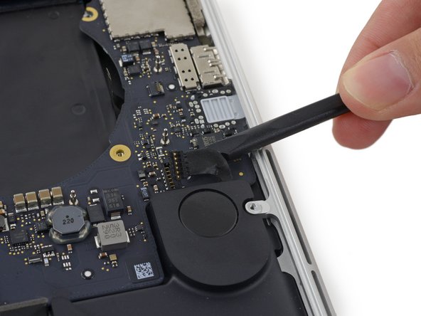
スパッジャーの先端を使って、カメラケーブルコネクターを基板上のソケットから押して接続を外します。
This connector is very fragile, the left edge of mine cracked off and ended up in the socket. And during figuring that out the cable or the socket appears to have got damaged because “no camera detected”.
Yeah, same here.. Not sure what to do now
Have you found a solution to this problem ? I have the same issue
All connectors are incredibly fragile. I damaged the fan connector locking latch just by trying to lock it back in place. Fortunately the cable, by the way it inserts, it’s being pushed in rather than pulled on, however, I do have concerns with it not making a proper connection. Malcolm, I am wondering how you fixed your damaged connector?
The connector slides into the socket so using the flat end of the Splunger under the cable and gently lifting draws the connector apart.
Don’t use the flat edge of the spudger. Instead, use the pointed end to gently slide off by the dog ears of the plug. If you look closely you’ll see a notch on each side.
supplied tool does not have a fine enough point here - won’t move at all
I used the fine point and also used the tweezers under the plug to relieve some pressure. I was very, very careful and made small moves. I seemed to get it out with no damage.
Al Moulder - 返信
Thanks for your comments guys! The ones about the twiners were a BINGO! :-)
-
-
-
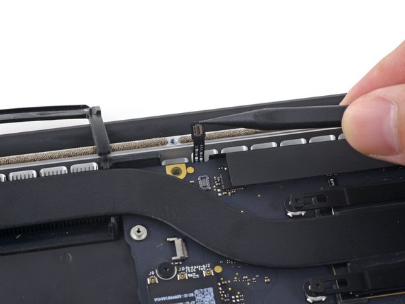
指を使ってAirPort/カメラケーブルをファンから引っ張ります。
-
ゆっくりとプラスチックのケーブルガイドからケーブルを巻き戻します。
Leave them attached. Remove the single screw holding the board in place and gently wiggle the airport card out (see Airport card removal instructions). Fold the card up and towards the rear of the computer. Now follow the instructions for the camera cable removal. Lift the airport card with the three leads attached and the camera cable up and fold the, to the outside of the case.
This video shows how to do it safely: https://www.youtube.com/watch?v=AabLlHT5...
Undo the 3 cables gently. remove the airport card. gently pry away the cables fro the fan plastic. then the camera cable will slide out easily.
I was afraid to just pull on any cables adhered, so I used a spudger edge to very gently “scrape” them up instead.
It was much easier following the instructions on the YouTube video, thanks! Looks like the process starts around 4:11.
why are we completely tearing the computer, just to replace the battery?
surely tearing it down could do more damage than being careful removing the bloated battery
-
-
-
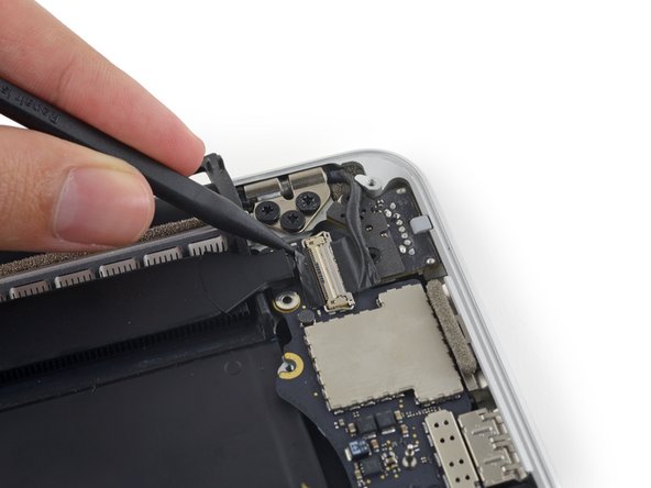
I/Oボードケーブルのコネクターカバーを固定している2.2 mm T5トルクスネジを4本外します。
why is this needed for upper assembly replacement?
Andrew Chu - 返信
My cable connector covers are not screwed down. Mid 2015 15” MBP. That’s the computer in the title of this article so idk.
I’m having trouble breaking the 2.2 mm screws loose and I don’t want to strip the head. I’m using the T5 screwdriver. Does anyone know any tricks or suggestions?
Ok, so the correct size Torx is the T4, not T5
Is this really necessary just to replace the LEFT speaker?
I'm replacing the speakers and one of these 4 screws is longer than the others. unclear of it's size so it helps to pay attention to the size/what they look like when taking them out!!
Tj Bennett - 返信
-
-
-
右側のコネクターカバーを取り出します。
-
スパッジャーの平面側先端を使って、基板上のソケットから I/Oボードケーブルの右側先端をこじ開けます。
-
-
-
基板に右側ファンを取り付けている次のネジを外します。
-
5.0 mm T5トルクスネジー1本(2.0mm肩付き)
-
4.0 mm ネジー1本
-
4.4 mm ー1本
The orange colour coded one is more mushroom shaped than the other screws (their size is not easy to otherwise tell apart)
-
-
-
スパッジャーの先端を使って、右側ファンリボンケーブルのZIFソケット上にある固定フラップを裏返します。
A note about these ZIF sockets - the retaining flap is just held in place by the small amount of friction, and on reassembly they can separate. I learned to push them down with my finger when possible, or else with a flat end, carefully walking them down side by side to keep it as even as possible. If the flap separates all is not lost ! It’s quite difficult (I did almost everything in this guide with tweezers under magnifiers) but if you remove the cable first, you can get the plastic “comb” back under the pins and up into it’s original position, then replace the cable and try again.
I was gonna comment that I broke the retaining flap off the connector, but per Matt’s comment above I guess it just separated off.
Anyways while holding the flap part in a pair of needle nose tweezers the tweezers closed and shot the flap off like a bullet somewhere in my living room lol. So be careful if it does separate on you haha.
These plugs are HORRIBLE. Make sure you only pull the ribbon. All three of my ribbons came off with the plastic clip, and they are impossible to put back on. I broke all three of these the same way. (Both fans and the mic) Everything else was pretty easy. Anyone need a door stop?
-
-
-
ファンを持ち上げて、ソケットからファケーブルを解放するため、ゆっくりとMacBookの後ろ側端に向けて押し出します。
-
ファンを取り出します。
I recommend pushing the cable connector away with a spudger instead of using the fan to pull it away…there seems to be too much stress put on the cable using the method proposed here.
Using a spudger does help alleviate stress on the cable. I also used it to help get the cable up from being adhered to the logic board.
Adding to the other comments, the fan is very light and has no resistance lifting out of the place it sits in.
I carefully lifted the fan just before there was any tension on the cable.
With the fan held in my right hand and spudger in my left, I moved the spudger under the fan approaching from the left side.
This allowed me to easily place the flat end of the spudger under the cable where the thicker plastic sits and gently pry the cable up until the cable broke away from the body.
I then used the pointed part of the spudger to gently pry the connector part of the cable away from the socket while gently pulling the fan away until the cable was disconnected and the entire fan was free.
Terrible instructions on this one. I thought I was supposed to pull the cable off the bottom of the fan! Not photos showing the final result. Finally the cable on the right came away from the board and out of the socket with the flap lifted up. Please make this clearer or damage to the cable can take place.
Instructions are faulty. After removing fan screws and lifting the retaining flap, lift the fan with one hand while gently pushing the connector with the flat side of a spudge toward the back of the chassis. It should slide off.
I definitely needed to use the spudger to gently lift the cable from the board while holding the fan with one hand. The cable was stuck on the board pretty well. Once I broke the seal it was a simple case of pushing it out of the connector.
Al Moulder - 返信
-
-
-
-
基板に左側ファンを固定している次のネジを外します。
-
3.6 mm T5トルクスネジー1本
-
5.0 mm T5トルクスネジー1本
-
4.4 mm T5 トルクスネジー1本
the yellow one may not go back in during reassembly unless the board is perfect. Stripped mine in the effort - put back together without this screw :(
I ran in a similar misalignment so had to bend the top left loop a bit to make it fit.
Not a big issue, but better to lay it in and check the alignment of all screw holes (and adapt if necessary) before putting the screws in.
I saw my replacement part had already a bit of paint missing at the top left and bottom right holes, so I assume it is a refurbished or sourced part, so a bit of tweaking may be necessary. BTW, the fan works perfectly, no more annoying clicking noises.
The red-coded one is the most mushroom-shaped screw this time. (biggest, flattest screw head)
-
-
-
スパッジャーの先端を使ってI/Oボードのコネクター上のロック機能を持ち上げます。
-
スパッジャーでこれを反対側に裏返して、スパッジャーの平面側先端を使ってコネクターからI/Oケーブルをスライドします。
The locking-bail is on the the cable part of the connector.
I think it would be easier to understand if there was a picture showing how the connector slides out
Owen Smith - 返信
-
-
-
I/Oボードから3.1 mm T5トルクスネジを2本外します。
Remove the screw holding the heat pipe, it blocks the I/O board from coming out
It's interesting that you had to remove the heat pipe screw. This didn't seem to be in the way for me. The I/O board came out quite easily without any issues.
But… it could be different for others as it was for you. I just thought I'd share my experience.
Thanks for the tip! I also had to remove that screw to get the board out.
The board was not coming out for me until I removed that heat pipe screw. Thanks for the tip!
Also make sure the I/O cable removed on previous step is out of the way before screwing this down
Keith Kern - 返信
Me too. The heat pipe screw overlapped the I/O board slightly, but very securely held it down on mine. Had to be removed.
-
-
-
ゆっくりとI/Oボードの内側の先端を持ち上げて、MacBookの中央側に向けて引っ張り、ケースから解放します。
-
I/Oボードを取り出します。
You do not need to undo all the screws, just the thin strip over the battery and the battery connection to the motherboard. I used isopropyl alcohol and a metal business card to slide under the battery and worked my way from left to right. Cover the leading edge of the metal business card with isopropyl and it will be easier, it deteriorates the glue and eases the process. Took 5-7 minutes. Tried to add photos to show it was possible, but this site wouldn't let me.
-
-
-
基板にtouchpadケーブルコネクターを固定している2.2 mm Torx T5トルクスネジを2本外します。
-
カバーを取り出します。
I'm confused why it's necessary to remove the entire logic board to replace the right speaker?
Don't you just need to remove the I/O board for the right speaker?
-
-
-
基板アセンブリを上部ケースに固定している次の6本のネジを取り外します。
-
3.8 mm T5トルクスネジー1本
-
5.7 mm T5トルクスネジー2本
-
5.6 mm T5トルクスネジー1本(このネジはシルバーで他のネジに比べると若干高くなっています。)
-
2.6 mm T5トルクスネジー1本
-
3.2 mm T5トルクスネジー1本
This step is really best done after all the cables are removed (Step 40).
maccentric - 返信
On the other hand, when reassembling, keep the screws until this step 29
The red screw above is the same one I had to remove to remove the I/O board back in step 24
Al Moulder - 返信
You should really do this colorblind-proof...
-
-
-
次の手順では下の6つのコネクタの接続を外します。各手順をしっかりと読んでから作業に移ってください。これらのコネクタのタイプは様々で、外し方も異なります。
-
マイクケーブル
-
左側スピーカーケーブル
-
キーボードデータケーブル
-
右側スピーカーケーブル
-
キーボード用バックライトケーブル
-
ディスプレイデータケーブル
Save this step until you get to step 40
I would wait until after step 39 to remove these screws. Once they are removed, the logic board jiggles around and makes disconnecting the various cables in 31-39 more difficult.
Agree with Daniel Christie. Wait until step 39.
-
-
-
スパッジャーの先端を使ってマイクリボンケーブルのZIFソケット上の固定フラップを裏返します。
-
ソケットからマイクリボンケーブルを基板と並行に引っ張ります。
This cable was pretty hard to remove at first. I had to gently wiggle it from side-to-side in the socket before it would let go.
I had the same issue. This was the hardest cable to remove imo. i was afraid i was going to tear it which as hard as i needed to pull it. I ended up leaving this cable inserted until the logic board was fully unscrewed to give me a bit more wiggle room.
-
-
-
スパッジャーの平面側先端を使って、左側スピーカーのコネクタを持ち上げて、基板上のソケットから接続を外します。
-
ケーブルをゆっくりと折り曲げて、基板から離します。
this cable was stuck down, so I had to wiggle the spudger under the cable first to separate the adhesive. Then it came away easily.
Same here, the cable was stuck down pretty. Thanks Pete, your advice helped a lot.
-
-
-
キーボードデータケーブルコネクタの上部を覆っているカバーを外します。
I wasn’t able to re-stick my tape during reassembly, not sure if that will cause issues but I’m not sure how to fix it.
-
-
-
スパッジャーの先端を使って、キーボードデータケーブルZIFソケット上の固定フラップを持ち上げます。
-
キーボードデータケーブルをZIFソケットから引っ張り、基板と並行に折り曲げます。まっすぐ上向きに引っ張らないでください。
The retaining flap broke on me during reassembly. I was careful, but it kind of got stuck. Pay extra attention and if it doesn’t give, don’t force it.
Same thing happened to me. Didn’t really put much pressure either.
meadowsd -
Same there here.. I ended up using some tape to ensure the cable stayed seated upo nreassembly
hey its not a kick, take it easy on it. after replacing my battery my keyboard (and not Richards keyboard) and track pad are non responsive, Russell Stewart old neighbour .
The last picture doesn’t show it but my cable had blue plastic material on both top and bottom, which I had not noticed during disassembly. It slid in nicely but now not sure if it is an insulating material of some kind that should have been set aside?
I can confirm blue colour of cable tip.
The retaining flap broke off on us during reassembly also…we (husband/wife team) were very careful, but the center piece just broke out when we applied pressure. the blue material did fit under the cable socket (like a smooth blue ribbon), but without the retaining lock, was unsure it would stay in position. We pulled the tape over it and hoped all would work. Everything seems to be working fine for us.
The retaining flap broke on me as well and caused a near panic. I actually managed to fix it by careful inspection under magnifier and some trial and error with tweezers. The retaining flap itself is comb shaped - a solid edge and then combs that come out between the wires., and apparently just held in by the tiniest of detents. After trying unsuccessfully to push it back down between the wires, I surmised that the gaps in the “comb” side for the wires were sealed loop and that the wires it sat on were open ended. So I eventually ended up lining the flap up as if it were closed, and then carefully nudging it up onto the top wires, which was succesful, and then pushing it back into the open position to get the detents in place. Then to close it after reinserting the cable I walked it down bit by bit by pushing forward and *downward* on each side to help it maintain it’s ‘hinging’ effect. I think frankly you’re better off pushing larger ones like these down with your finger instead of a tool.
To close my retainer during reassembly I ended up using the side of the iFixit spudger. I pressed against the entire length of the retainer in order to apply equal pressure along the whole thing. It seemed to work well.
-
-
-
スパッジャーの先端を使って、右側のスピーカーコネクターをこじ開けて、基板上のソケットから接続を外します。
-
ケーブルを基板から邪魔にならない位置に丁寧に折り曲げます。
There's not much space here to work with. I found it helpful to remove the screws holding down the battery board, which allowed it to be lifted out a bit for easier access to this connector.
maccentric - 返信
I used the tweezers on this and that was very effective in popping this cable out.
Al Moulder - 返信
-
-
-
スパッジャーの先端を使って、キーボードのバックライトコネクターを基板上のソケットから接続を外します。
On reassembly it would be great to have some tips on how to properly locate this connector…it’s kind of fussy.
Thanks for calling this out. I took a picture of the socket after disconnecting. I can see why it might have been less obvious on reassembly.
Also on reassembly - when putting in the logic board make sure this connector is not underneath. Once you have the logic board in, double check and if needed you can slightly lift up the logic board (like to take it out) and use the spudger to scoop it out.
I found that this was actually really easy to get back on by using my finger instead of a tool, as I could just wiggle it back and forth slightly until I felt it seat. Hopefully using your fingers isn’t verboten - I was strapped in at the time and everything worked out in the end.
the picture is mirrored
The picture is not mirrored if you see the heat sink that curves to the up and left it is not mirrored.
-
-
-
スパッジャーの先端を使って、ディスプレイデータのケーブルロックの接続を持ち上げて、MagSafe 2パワーポート側に折り曲げます。
+(mit dem schwarzen Klebeband zusammen)
Verwende die Spitze eines Spudgers, um den Verschluss des Displaydatenkabels nach oben zu klappen (mit dem schwarzen Klebeband zusammen) und ihn in Richtung MagSafe 2-Powerport zu drehen.
-
-
-
ディスプレイデータケーブルをまっすぐ基板上のソケットから持ち上げます。
-
ディスプレイの蝶番側に向けてディスプレイデータケーブルを丁寧に折り曲げます。MagSafe 2ボード上のネジが触れるようにします。
The wording of the instruction: “Pull the display data cable STRAIGHT OUT of its socket on the logic board” could lead to errors. It almost happened to me.
Instead you should word it: “Pull the display data cable parallel to the face of the logic board being careful to keep it straight and NOT LIFT UP on the cable”.
I realize you mention it later in the warning immediately below, however, by first saying “pull the cable straight out” leads to confusion and could lead the user to attempt to interpret “PULL STRAIGHT OUT” as “PULL UP” unsuccesfully only to later notice, maybe after breaking it, that there was a warning.
Wording it properly the first time will make the warning unnecessary.
I had the same thought as I almost proceeded without noticing the red text warning.
I especially think the second warning about not touching the contacts on the data connectors should be listed before the instructions on removing it.
I think it bears repeating just how fragile this connector is, particularly on reinsertion. The problem isn’t just technicians touching the connector end; you can damage the pins simply by inserting it slightly out of alignment, or at an angle, because the outermost pins are VERY close to the edge and are very fragile. They have the appearance of being embedded in the connector but they’re actually spring traces just lying on top of it. I managed to bend the southmost pin upwards reinserting it; luckily it flattened out again and worked, but if it had not been possible to do that it’d have been a whole new screen assembly.
I’m pretty sure I inadvertently touched the connectors. Would this cause immediate errors or obscure, difficult-to-diagnose problems later in life ? Also strongly suggest using magnification when disconnecting and reconnecting this connector and others to ensure proper alignment. As Jerome said these are some of the most fragile parts of the system.
I'm jumping on the bandwagon here and saying that yes, pull the cable out towards the right (where the MagSafe connector) and not up. I also found using the tweezers made this easier.
Big fan of the tweezers.
Al Moulder - 返信
I can't stress this enough - again: This connector is extremely fragile. After changing the right speaker and putting everything in place my display went black. Gone. Tried with the display data connector's"out an in again" very carefully - nothing. The professional technician at the service shop I asked told me he wouldn't touch that particular connector ever again.
I mean, why the logic board disassembly? Only because the speaker's cable is placed under the logic board? Why not cutting the old cable without removing the logic board and putting the new speaker in, placing the cable on top of the logic board? To avoid the necessity of disconnecting the display data connector at all costs?
-
-
-
MagSafe 2ボードから4.0 mm T5トルクスネジを2本外します。
I didn’t take these out - just lifted the mainboard away and set it to the back while I removed and replaced the left speaker.
on my Mid 2015 MBP the MagSafe 2 board is wired to the logic board on the underside (keyboard side) so the screws had to come out. The following photo showing the logic board coming out does not show the MagSafe 2 board, so there is clearly some variation between these models.
-
-
-
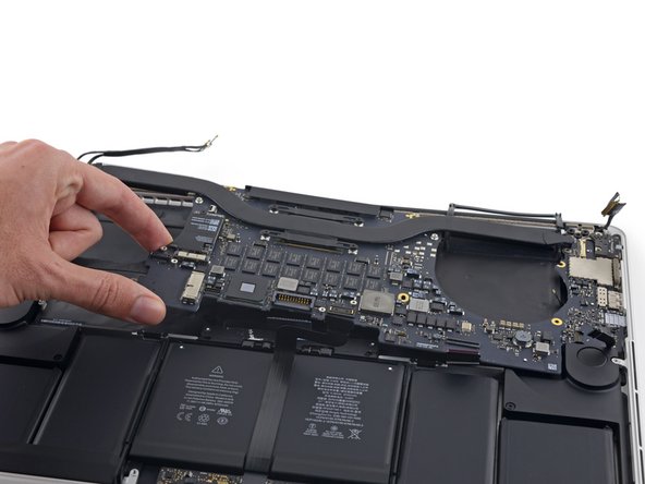
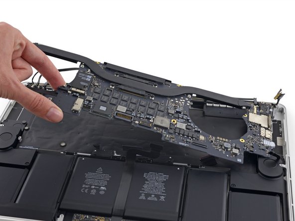
上部ケースから基板アセンブリ全体を持ちあげて取り出します。
When reassembling, be careful not to leave any cables (such as keyboard backlight connector, step 36) under the board.
I had to tape most of the cables out of the way while reinstalling the logic board, because they kept returning to their plugged-in shape under the logic board as I tried to position it properly.
Also, make sure to align the right (and left) I/O properly, making sure the tabs on each port are underneath the lip of the aluminum frame. In my case, I couldn’t push the logic board far enough to align the screws until I had done this.
Yes. This step is crucial. Thanks for pointing it out!
jonvdez -
I was struggling to align it and was beginning to get frustrated. I had to look back at photos to make sure the tabs had to go under the lip of the aluminum frame. Unfortunately I read your comment after the fact. Thank you.
if you’re only removing the right speaker, no need to remove the logic board. Simply lift the edge of the logic board to remove the speaker cable.
I had to remove one of the screws from the battery board before the logic board had enough clearance to lift up.
Jim Guyton - 返信
We (husband/wife team) just slid the logic board out to right, and did not entirely remove. For reassembly, we reviewed all the cables and made sure they were positioned out of the way, or taped back, before repositioning the logic board back into position. Worth it to review before getting it back into position.
Does the logic board prevent us from removing the battery? I’m trying to figure out why we are removing it.
I agree John, tearing everything out is more of a risk then could be done ungluing the battery
Because the acetone can damage the board and connections -- in case of accident ;)
kevin -
why is the heatsink still attached?
-
-
-
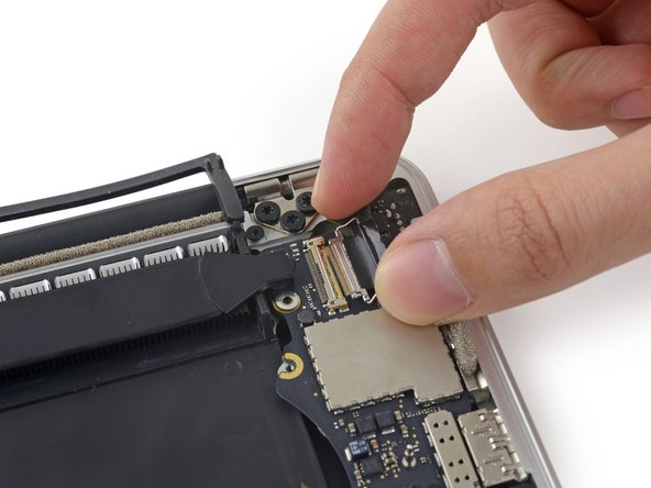
スパッジャーの先端を使って、HDMIデータトランスポートケーブルのメタル製固定フラップを押し上げてください。
-
基板上にあるソケットからHDMIデータトランスポートケーブルを丁寧に引き上げて接続を外します。
-
-
-
MagSafe2コネクターを(ロジックボードと平行している)ソケットからまっすぐ引き抜きます。
-


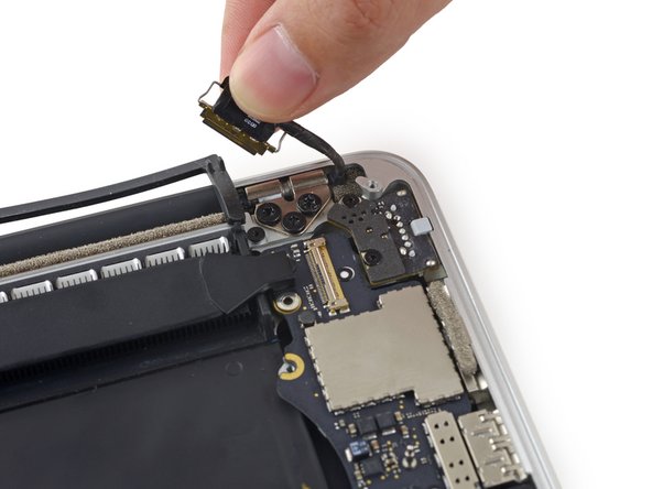


デバイスを再組立てする際は、これらの手順を逆の順番に従って作業を進めてください。
デバイスを再組立てする際は、これらの手順を逆の順番に従って作業を進めてください。
82 の人々がこのガイドを完成させました。
以下の翻訳者の皆さんにお礼を申し上げます:
100%

これらの翻訳者の方々は世界を修理する私たちのサポートをしてくれています。 あなたも貢献してみませんか?
翻訳を始める ›

12 件のコメント
Any tips on where to purchase a replacement logic board?
Isaac Hake - 返信
Can i use the mid-2015 logic board to mid-2012?
This logic board is the model whit just one graphic card, in the other model the logic board have one IC close to processor
Can the heatsink be removed without taking out the logic board?
i have a mid 2015 2.5ghz MacBook pro. Can I replace the defective logic board with the 2.8ghz logic board?
geomatrixx - 返信
thanks, i managed to clean up my mac and change cpu and gpu thermal paste. finally, no underclocking when reaching high temps!
I have mid 2015 2.2 ghz integrated logic board… Can I replace it with a mid 2015 dual graphics 2.8 ghz???
is it possible to skip steps 14-20 to replace a logicboard with fans attached on it ?
I got a logic board to swap RN and it already has the fans. So I think so, right? Gotta try
The number of screws listed here is wrong on my model. I had four of the smaller size.
anonymous 1286 - 返信
Just to add to my comment above (I can't edit it because it's anonymous), my MacBook Pro is a mid-2015 15in model 2.8GHz (A1398; EMC2881). For the bottom case it uses six 3.1mm screws, and four 2.3mm screws at the clutch/hinge side of the MacBook Pro. I tried using a 3.1mm screw at the clutch/hinge end, as described in the main article, and they don't fit. It has to be four 2.3mm screws.
anonymous 1286 - 返信
agreed with above 1286...
I have the Mid 2015/A1398/EMC 2909. the hinge end and two middle side screws used a 1.2x50mm screwdriver while the 'opening' end 4 screws used the T3 screwdriver. I guess different builds used different sized screws!!
Tj Bennett -
The instructions below have you basically taking ALL of the guts out of case. I’ve been doing my own apple repairs since before ifixit was a thing and this one is a handful. My battery was swelling and I wanted to remove it before it burst or bent the case so I took it out without having a replacement and it occurs to me that aside from using the solvent (liquid) to remove the adhesive, you could probably do this only taking the trackpad ribbon out. I have mine reassembled now and will research the best battery to buy but I think installation will take about 5 minutes. See if you can slip a plastic gift card under the battery and wag/saw the adhesive out without the solvent before you go through all of this. It might work. Note, don’t bend or put too much stress on the battery and certainly don’t puncture it…
br1ansk - 返信
Battery Recall for 15-inch MacBook Pro Retina mid-2015. Check Apple’s site for recalls, and put in your serial number. They replaced my swelling battery for free, regardless of warranty.
Steve -
As we are only replacing the battery, you can safely skip steps 6-26 and 28-48, no need to disassemble the computer to pull out the battery. Use nail polisher remover I was able to pull a super bloated battery out, without disassembling my MacBook.
John Sikking -
I qualified for the recall. These bloated batteries are dangerous! DO NOT, UNDER ANY CIRCUMSTANCES, PUNCTURE THE BATTERIES!
Thanks for the heads-up on the recall.
Datajockeys -
For battery replacement, I also chose NOT to remove everything, and NOT to use the solvent. I used an iFixit heating tube (from the iPad kits) to soften the adhesive from the keyboard face… NOT the battery itself! Used the iFixit cards. I have four, so the real work is possible BETWEEN two other cards — reduces the chance of puncturing the battery. Worked fine, took a little while, but no problems.
Steve -
I’m having a problem trying to get the screws off. I have a set of pentalobe screwdriver set. I found one screwdriver that fits perfectly on one set of screws, but I am unable to unscrew it. I tried using some force pushing the screwdriver into the screw, but nothing happens. Any suggestions?
henry_k_wong - 返信
All the screws on mine are the same length for some reason.
ccfman2004 - 返信
I would recommend the first step is: Run the battery down to ZERO before doing any next step. This reduces risk to you, people nearby, to the MBP and greatly reduces the risk of fire. Step 2 should be: Double-check that the battery is at zero.
I like others listed below and on YouTube, disagree with these full tear down 70+ steps being the only focus. I get that I have to be careful not to get the acetone solvent near the speakers. I skipped 25+ steps by: tilting the MBP away from the speakers and using very little acetone solvent. More pressure with the plastic cards and only a few drops of solvent. While giving the full set of instructions is fine it should be very clear that you can (at the user’s own risk) do this.
Kenneth Schleede - 返信
As above—I consider full disassembly to be far riskier to fragile cables and connectors than the risk for solvent spillage. I did steps 1-5 and 46-74. No issues. I HIGHLY recommend the iFixit magnetic Project Mat. It’s a white marker board surface gridded into squares and invaluable for labeling part sizes/steps in disassembly.
philtrit - 返信
As above too. I benefitted from the advice. From step 51 onwards, I found a easier way using tip from China battery seller. Use a 2” width plastic scraper/plastic paint scraper to poke under the battery. Use moderate strength to poke and avoid rough handling of the battery so as not to puncture it. There is no need to pry the battery to avoid stressing it, just use a firm poking action under the battery and the double sided tape adhesive will yield. After 5 min of such poking, the entire battery pack can be removed without the hassle of pouring the adhesive remover from step 51 onwards. Get a scraper with a stronger handle so that it is more comfortable to poke.
https://www.aliexpress.com/item/32889670...
Emma Pn - 返信
Heads up as you go…we (husband/wife team) had a notebook that when screws/covers were removed, we marked the step # and actually taped the screws into the notebook noted by the step number. This was very helpful on reassembly and we knew we would be using the exact screw into the original screw hole.
Ann Brainard - 返信
After replacing the batteries myself, I wouldn’t even consider doing it again. Not that it’s difficult to do—that’s not the issue. The issue is aftermarket batteries. I’ve been using notebooks for well over 30 years, and never had satisfaction with aftermarket batteries.
Modern lithium batteries are an amazing technological feat, but a dangerous one. So even putting aside that I’ve never found any aftermarket batteries with quality anywhere near original, I learned “cheap” aftermarket lithium batteries are downright dangerous.
After doing research into what’s involved with manufacturing lithium batteries, I know there are so many corners to cut, you’ll end up with junk regardless of what you pay.
A week after replacing my batteries with those from iFixit, they showed clear signs of failure. Thank goodness iFixit refunded my money.
After having Apple replace my batteries, everything is back to like-new. For my $199, I got not only excellent batteries, but a new keyboard and trackpad as well. That’s it’s done!!!
AnnoniMoose - 返信
Which of the following companies make their own LiIon cells, Apple, Dell, DeWalt, Milwaukee, Tesla, Trek? Ans: NONE OF THEM. All these companies buy their LiIon cells from companies that will sell to iFixit or any other legitimate company. If you want quality, either do the research or pay through the nose for OEM. And note the Apple battery recall. Apple messes up too.
Bartwick -
I found an Apple Support link that said MBP battery replacement was $199, but the 2 Apple Stores near my house would not provide any appointments. Instead, I scheduled an appointment with and “Apple Authorized Service Provider” & that repair center quoted about $750 to replace the battery.
I refused, went home, & opened a chat with Apple Support.
After a lengthy & painful chat session where the Apple tech didn’t want to provide a battery replacement quote (he feared other issues with the MBPr), he finally gave me an Apple price of just under $650 to replace the battery.
Did you go into an Apple store, or mail it in? I’m struggling to reconcile a price of $199 to get a battery + keyboard + trackpad against what I was just quoted 2 weeks ago. The new track pad & keyboard might have been due to repair tech error. i.e. they trashed those repairing your batter & had to toss them in.
Bartt.Shelton@gmail.com - 返信
I took mine in after being quoted for a $199 replacement of battery and keyboard, only to have the repair refused as they found a "water sensor" triggered and now I'm left with my AUD$5,000 laptop with messed up keys. Shame on me for not getting this repaired during COVID while under warranty. This is the first time I've truly been disappointed in Apple, but suppose it was bound to happen someday. I was quoted US$ 1479 to replace the battery and keyboard and the sensor (likely the logic board is replaced as well) if I were to send it in to the US repair center. Any chance these sensors can be triggered by humidity?
C0RT - 返信
I 1000% recommend watching this video and performing the battery replacement without all these steps from this guide and without using the acetone solvent. https://www.youtube.com/watch?v=ImonCWcc... (15" inch Retina MacBook Pro A1398 Mid 2015 Disassembly Battery Replacement Repair)
The video is narrated well and the guy goes slow and zooms in where appropriate. Instead of removing all components, he simply removes the track pad cable, battery cable, and unscrews two of the speaker screws on each side. From there, you can lift up the speaker arms where the video guy uses a thin pry tool to push through the sticky tape. No solvent is needed except for residual sticky stuff leftover.
Instead of the thin pry tool, I just used the plastic cards that came with this ifixit kit. It takes a little force and wiggle/jiggle so take your time using the corner of the card to start.
This method makes a difficult 2-3hr job into a much easier 1hr job.
Spencer - 返信
+1 for this approach! I watched the video that Spencer mentioned. It took me a little over an hour, and it was stress-free. https://youtu.be/ImonCWcc1xk
Chris Wicklas -
Another +1 - I followed the video pretty exactly (after having already gone through steps 1-5 here). I'm not sure it's necessary to clean off the adhesive residue as thoroughly as he demonstrates in the video, but the instructions were clear and the end results were good - trackpad still working fine and new battery already charged to 50%.
Jeff Zinn -
Glad I read these comments before plunging into the iFixit instructions.
+1 for skipping the iFixit instructions and using the youtube video linked by Spencer.
I followed the instructions and had my battery replacement done succesfully.
Instead of the metal spatula like thing he used - I used the plastic ifixit credit card things that came with my battery kit.
It took about 15 minutes of wiggling under the battery to free it from the adhesive but it wasn't too bad.
I did remove the residual adhesive as he indicated with isopropyl alcohol - but after finishing my installation I realized it was completely unnecessary. You can install the new battery over the residual gunk and skip that step.
picardo -
Yes! This YouTube tutorial works great and it was really easy to replace the battery. I needed about 75 minutes.
Perform steps 1-5,
Then skip to step 41.
In 41 + 43 do not unscrew the red marked screws.
In 42 an 45 just lift the speakers, do not remove them.
Skip 44
Up from 53, I did not use the glue remover, the plastic cards were enough.
In step 63 watch out to start from the middle. This prevents you from peeling up the lower „platform“.
Great job :-)
weekendiac -
It’s now February 2024, and the batteries Apple installed have all swelled up just like the originals. Doing a bit of research on the manufacturer, Simplo, I no longer trust them either. Microsoft used Simplo in their tablets, with countless users complaining about bad batteries. A few days ago, I read a post saying Apple now charges $250 instead of the $200 I paid less than three years ago. WOW! Even if Apple would replace my batteries, there’s no way I’m going that route again. Too bad my MacBook won’t boot without batteries. I don’t need them; I don’t want them. I also don’t want a newer MacBook. What to do???
AnnoniMoose - 返信