メインコンテンツにスキップ

このバージョンは誤った内容を含んでいる可能性があります。最新の承認済みスナップショットに切り替えてください。

必要な工具と部品

  1. , 下部ケースのネジを外す: 手順 1、 1の画像 1
    • MacBook Pro 13インチ Unibodyに留められた底ケースから次のネジを10本外します。

    • 3 mmプラスネジー7本

    • 13.5 mmプラスネジー3本

  2. , 下部ケースを持ち上げて外す: 手順 2、 1の画像 1
    • 取付台タブを外すため、底ケースをわずかに持ち上げて、デバイス本体の背中側に向けて押します。

  3. , バッテリー: 手順 3、 1の画像 1
    • 作業前の注意点として、放電を防ぐためロジックボードからバッテリーコネクターの接続を外してください。

    • スパッジャーの平面側先端を使って、ロジックボード上のソケットからバッテリーコネクターを持ち上げます。

  4. , ファン: 手順 4、 3の画像 1 , ファン: 手順 4、 3の画像 2 , ファン: 手順 4、 3の画像 3
    • ファンコネクタを基板上のソケットからファンコネクタを引き抜きます。

    • コネクタの接続を外すには、ファンケーブルのワイヤ下からスパッジャーでツイストしながら作業をすると上手くいきます。

    • ファンのソケットとファンのコネクタは2番目、3番目の画像で確認できます。スパッジャーを使ってファンのコネクタをまっすぐソケットから引き抜く際に、基板に付いているプラスチックのファンソケットを壊さないようご注意ください。基板のレイアウトは2番目の画像で確認できますが、お手元のデバイスのデザインと若干異なることがあるかもしれません。ファンソケットは同じはずです。

  5. : 手順 5、 1の画像 1
    • 次の3本のネジを外します。

    • 7 mm T6 トルクスネジー1本

    • 5.4 mm T6トルクスネジー2本

  6. : 手順 6、 1の画像 1
    • 上部ケースからファンを取り出します。

  7. , 基板: 手順 7、 3の画像 1 , 基板: 手順 7、 3の画像 2 , 基板: 手順 7、 3の画像 3
    • ディスプレイデータケーブルのロックに固定されたプラスチックのタブを掴んで、コンピューターのDC-Inサイドに向けて回転させます。

    • ゆっくりとディスプレイデータケーブルのコネクタを基板と並行に引っ張ります。

    • コネクタを上向きに引っ張らないでください。コネクタにダメージを与えてしまいます。

  8. : 手順 8、 2の画像 1 : 手順 8、 2の画像 2
    • ディスプレイデータケーブルのブラケットに上部ケースを固定している2本のネジを外します。

    • 8.6 mmプラスネジー1本

    • 5.6 mmプラスネジー1本

    • ディスプレイデータケーブルのブラケットを上部ケースから持ち上げます。

  9. : 手順 9、 1の画像 1
    • スパッジャーの平面側先端を使って、サブウーファーと右側スピーカーのコネクタを基板から引き上げます。

  10. : 手順 10、 1の画像 1
    • カメラケーブルコネクタを光学ドライブ側に向けて引っ張り、基板から接続を外します。

    • このソケットはメタル製で簡単に曲がってしまいます。コネクタを基板上のソケットと接続させる前に、位置を合わせて確認してください。

  11. : 手順 11、 3の画像 1 : 手順 11、 3の画像 2 : 手順 11、 3の画像 3
    • スパッジャーの平面側先端を使って、光学ドライブ、ハードドライブ、トラックパッドケーブルコネクタを基板から引き抜きます。

  12. : 手順 12、 3の画像 1 : 手順 12、 3の画像 2 : 手順 12、 3の画像 3
    • 爪先やスパッジャーの先端を使って、キーボードリボンケーブル用のZIFソケット上の固定用ケーブルを引き上げて裏返します。

    • キーボード用リボンケーブルをソケットからスライドさせるには、スパッジャーを使ってください。

  13. : 手順 13、 1の画像 1
    • キーボードバックライト用のリボンケーブルソケットから黒色のテープで小さな一片を剥がします。

  14. : 手順 14、 3の画像 1 : 手順 14、 3の画像 2 : 手順 14、 3の画像 3
    • スパッジャーの先端を使って、キーボードバックライト用のリボンケーブル用のZIFソケット上の固定ブラップケーブルを引き上げて裏返します。

    • スパッジャーを使って、ソケットからキーボードのバックライトリボンケーブルをスライドします。

  15. : 手順 15、 1の画像 1
    • スパッジャーの平面側先端を使って、基板からバッテリーインディケーター用ケーブルコネクタを引き抜きます。

  16. : 手順 16、 1の画像 1
    • スパッジャーの先端を使って、上部ケースに留められた接着剤からマイクを引き上げます。

  17. : 手順 17、 1の画像 1
    • 次のネジを外します。

    • 7 mm T6トルクスネジー2本

    • 3.3 mm T6トルクスネジー5本

    • 4 mm T6トルクスネジー2本

  18. : 手順 18、 2の画像 1 : 手順 18、 2の画像 2
    • 基板を取り出す前にバッテリーを取り出す必要はありませんが、基板を簡単に安全に取り出しやすくなります。バッテリーを残す場合は、基板をバーコード付近のバッテリーケース側に向けて曲げないようにご注意ください。

    • 上部ケースにバッテリーを固定している次のトライポイントネジを外します。

    • 5.5 mmトライポイントネジー1本

    • 13.5 mmトライポイントネジー1本

    • 上部ケースからバッテリーを取り出します。

  19. : 手順 19、 2の画像 1 : 手順 19、 2の画像 2
    • 上部ケースの横側がクリアになるまで、基板を左側から持ち上げます。

    • 上部ケースサイドから基板を持ち上げて取り出します。DC-Inボードが絡まないようにご注意ください。

  20. この手順は未翻訳です。 翻訳を手伝う。

    : 手順 20、 2の画像 1 : 手順 20、 2の画像 2
    • Remove two Phillips screws securing the hard drive bracket to the upper case.

    • The screws remain captive to the bracket.

    • Lift the the retaining bracket out from the upper case.

  21. この手順は未翻訳です。 翻訳を手伝う。

    : 手順 21、 1の画像 1
    • Lift the hard drive from its free edge and pull it out of the chassis, minding the cable attaching it to the computer.

  22. この手順は未翻訳です。 翻訳を手伝う。

    : 手順 22、 1の画像 1
    • Disconnect the hard drive by pulling the hard drive cable connector away from the drive.

  23. この手順は未翻訳です。 翻訳を手伝う。

    : 手順 23、 2の画像 1 : 手順 23、 2の画像 2
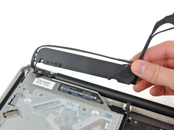
    • Remove the following four screws securing the hard drive and IR sensor cable to the upper case:

    • Two 1.5 mm Phillips screws.

    • Two 4 mm Phillips screws.

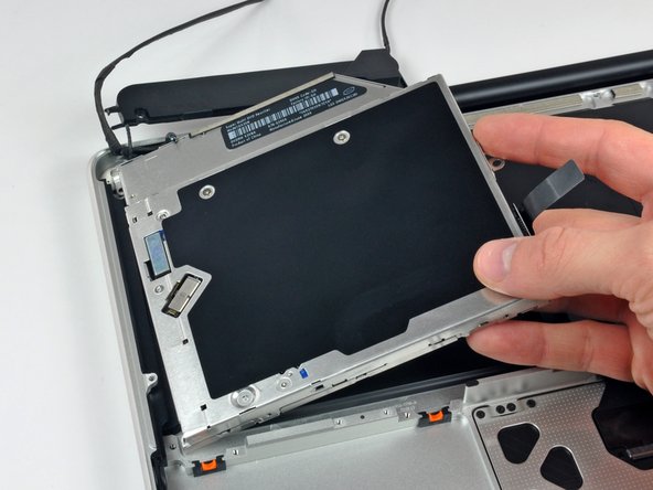
    • Slide the hard drive and IR sensor bracket away from the edge of the upper case.

    • Carefully peel the hard drive and IR sensor cable from the upper case.

  24. この手順は未翻訳です。 翻訳を手伝う。

    : 手順 24、 2の画像 1 : 手順 24、 2の画像 2
    • Remove the following screws securing the subwoofer to the upper case:

    • One 3.8 mm Phillips screw.

    • One 5 mm Phillips screw

    • The subwoofer is still connected to the right speaker, so don't completely remove it just yet.

    • Lift the subwoofer off the optical drive, and set it above the computer.

  25. この手順は未翻訳です。 翻訳を手伝う。

    : 手順 25、 2の画像 1 : 手順 25、 2の画像 2
    • Remove the two 10 mm Phillips screws securing the camera cable bracket to the upper case.

    • The leftmost screw may remain captive in the camera cable.

    • Lift the camera cable bracket out of the upper case.

  26. この手順は未翻訳です。 翻訳を手伝う。

    : 手順 26、 2の画像 1 : 手順 26、 2の画像 2
    • Remove the three 2.5 mm Phillips screws securing the optical drive to the upper case.

    • Lift the optical drive from its right edge and pull it out of the computer.

  27. この手順は未翻訳です。 翻訳を手伝う。

    : 手順 27、 1の画像 1
    • Peel back the small piece of black tape covering the right speaker cable.

    • Be careful, as the power button ribbon cable is directly under this piece of tape.

  28. この手順は未翻訳です。 翻訳を手伝う。

    : 手順 28、 1の画像 1
    • Use the tip of a spudger to pry the right speaker up off the adhesive securing it to the upper case.

  29. この手順は未翻訳です。 翻訳を手伝う。

    : 手順 29、 1の画像 1
    • Lift the subwoofer and right speaker assembly out of the upper case.

  30. この手順は未翻訳です。 翻訳を手伝う。

    : 手順 30、 2の画像 1 : 手順 30、 2の画像 2
    • Remove the two outer T8 Torx screws securing each side of the display bracket to the upper case (4 screws total).

  31. この手順は未翻訳です。 翻訳を手伝う。

    : 手順 31、 1の画像 1
    • Open your MacBook so the display is perpendicular to the upper case.

    • Place your opened MacBook on a table as pictured.

    • While holding the display and upper case together with your left hand, remove the T8 Torx screw from the lower display bracket.

  32. この手順は未翻訳です。 翻訳を手伝う。

    : 手順 32、 1の画像 1
    • Be sure to hold the display and upper case together with your left hand. Failure to do so may cause the freed display/upper case to fall, potentially damaging each component.

    • Remove the last remaining T8 Torx screw securing the display to the upper case.

  33. この手順は未翻訳です。 翻訳を手伝う。

    : 手順 33、 3の画像 1 : 手順 33、 3の画像 2 : 手順 33、 3の画像 3
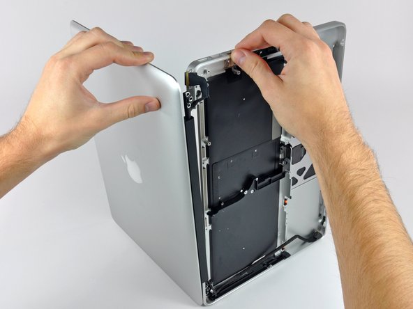
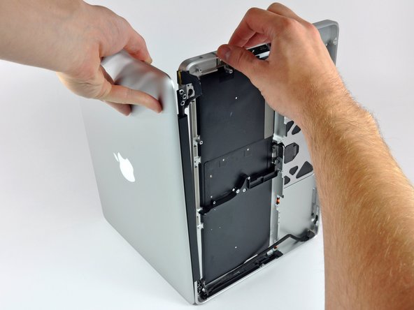
    • Grab the upper case with your right hand and rotate it slightly toward the top of the display so the upper display bracket clears the edge of the upper case.

    • Rotate the display slightly away from the upper case.

    • Lift the display up and away from the upper case, minding any brackets or cables that may get caught.

  34. : 手順 34、 1の画像 1
    • 赤でハイライトされた1.2mmプラスネジを4本外します。

  35. この手順は未翻訳です。 翻訳を手伝う。

    : 手順 35、 1の画像 1
    • Carefully dislodge the edge of the trackpad closest to the keyboard from its recess in the upper case by pushing it away from the brackets attached to the upper case.

    • De-route the trackpad cable through its slot cut into the upper case.

  36. : 手順 36、 1の画像 1
    • 上部ケースの外縁からトラックパッドを引き離します。

    • トラックパッドを取り外し、脇に置きます。

  37. この手順は未翻訳です。 翻訳を手伝う。

    : 手順 37、 1の画像 1
    • In the following steps, you will be working on your new upper case.

    • Use a T6 Torx screwdriver to loosely install the 1.1 mm set screw included with your new upper case into its tapped hole near the middle of the trackpad opening on your new upper case.

    • Only tighten it about one turn for now.

  38. この手順は未翻訳です。 翻訳を手伝う。

    : 手順 38、 2の画像 1 : 手順 38、 2の画像 2
    • Carefully insert the cable from your old trackpad through its slot cut into your new upper case.

    • Use one hand to hold the trackpad cable in place as you insert the two retaining tabs on the outer edge of the trackpad under the lip on the upper case.

    • Pull the trackpad cable as you seat the trackpad into its void in your new upper case.

  39. この手順は未翻訳です。 翻訳を手伝う。

    : 手順 39、 1の画像 1
    • Insert a 1.2 mm Phillips screw into each of the outer holes drilled into the trackpad (two screws total).

    • You'll install the rest in a bit.

    • Tighten the screws, then back them out about a quarter turn to aid in aligning your trackpad during the next few steps.

  40. : 手順 40、 1の画像 1
    • トラックパッドをクリックしようとし続けながら、カチッという音が工場出荷時の「感触」に戻るまでT6トルクス止めネジを慎重に締めます。

    • トラックパッドのカチッという音によって、ネジがきちんと締まっていることがわかります。止めネジが緩すぎると、カチッという音がする前にトラックパッドに遊びがあります。きつすぎると、トラックパッドはあまりにも容易にクリックできてしまうので、特徴的なマウスのクリックノイズが大きくなりません。

  41. この手順は未翻訳です。 翻訳を手伝う。

    : 手順 41、 1の画像 1
    • Next, flip your upper case over so the keyboard side is facing up.

    • Align the trackpad so it is centered in its hole cut into the upper case.

  42. この手順は未翻訳です。 翻訳を手伝う。

    : 手順 42、 1の画像 1
    • Tighten the outer two screws along the inner edge of the trackpad and check the alignment of it on the outer side of the upper case.

    • If its alignment looks good, install the rest of the Phillips screws along the inner edge of the trackpad.

    • Before reassembling your machine, verify that the set screw is still installed in a position so the mouse will click correctly.

ゴール

65 の人々がこのガイドを完成させました。

作成者

3人の作成者と共同で作成されました。

Andrew Bookholt

586,423 ポイント

619のガイドは作成済み

0 件のコメント

コメントを追加

統計データ:

過去 24時間: 5

過去 7 日: 17

過去 30 日: 49

今までの合計 76,759