はじめに
壊れたAirPortカードを交換して、Wi-Fiネットワークを回復させましょう。
必要な工具と部品
-
-
取付台タブを外すため、底ケースをわずかに持ち上げて、デバイス本体の背中側に向けて押します。
In the introduction you should link fixers to this excellent doc: https://www.ifixit.com/Misc/HD_Software_...
It is really critical, super easy, and free(!) to clone your existing drive onto the new one you will install. I ran into one error, but SuperDuper! support replied immediately on how to fix it...Thanks ifixit and SuperDuper! (I ponied up the $28 for the software anyway, I was so impressed!)
Long story short: I drank the AppleKoolAid back in 1984 and have always left the guts of my machines up to Apple - until recently when I needed to swap the SATAs from my original MacDaddy (2009 13" MBPro that I killed in 2018 - coffee + blackout = OOOOPS) into a pristine 2009 MBPro from a Goodwill in North Carolina through eBay. I need the files from iCal and MacMail that can't be opened in my newer machines.
Well . . . I ain't never done nuttin' like that, before!
Enter Luke Miani on YouTube. He raves about you guys! So, I watched everything I could, read your site, bought the right tools and at the ripe old age of 72, I sat down, this morning and did the work. Now my original MacDaddy lives in MacDaddy2.0.
Am I allowed to cry?
Seriously, I can't thank you enough for your bitchen site and killer tools. I wish I'd'a been turned on to this shizzle 30+ years ago.
IFIXIT - IDIGIT!
kath myers - 返信
HAHAHAHAHAHAHAHAHAHA.
That was a brilliant read.
Yes, I came across ifixit a few years ago. Totally helped me out on several occasions.
Glad your Mac repair journey worked out.
:)
Cary B -
-
-
-
スパッジャーの平面側先端を使って、ロジックボード上のソケットからバッテリーコネクターを持ち上げます。
How do you get that battery connector back on? Do you just press it in back in place after you're done?
yes. I usually plug it in before I screw it down so I can lift the battery a bit and have enough slack to be able to go straight down on the connector, otherwise it comes in on a bit of an angle, which can't be good (though not necessarily bad).
This step almost finished me, and I did extensive damage to the battery plug. Fortunately, I later replaced the battery, and the replacement came with a new plug! :) Newbies need to know - 1. The battery plug is like a thin lip on a thicker lip, so you need to pry BETWEEN 2 thin lips to get it off, else you are trying to yank out the socket. 2. Mine was initially VERY tight, and trying to get it out broke the plastic on all sides of plug, even though I was as careful as possible. Luckily, this didn't hurt functionality and I later replaced the battery. AFTER disconnecting once, it was never so tight again,
-
-
-
スパッジャーの平面側先端を使って、右側スピーカーケーブルコネクター/サブウーファーをロジックボード上のソケットから外して持ち上げます。
Please Be Carefully With This Step, Because I Had To Resolder It Back To The Logic Board. But There Is A Black Foam Piece Over The Cable You Have To Pry Up, Lift The Foam Piece And Then Try To CAREFULLY Pry Cable Connector
-
-
-
カメラケーブルを水平にスライドさせて、ソケットから外します。
-
ロジックボードにカメラケーブルがスライドして外れないように小さなプラスチック製リテイナー が付けられている場合は、ロジックボードから慎重に剥がしてください。必要に応じて、ヘアードライヤーやヒートガンで少し熱を加え、固定されている接着剤を柔らかくしてください。リテイナーを付けたまま、無理にケーブルを外さないでください。
-
それでも問題がある場合は、スパッジャーの先でコネクタの両側を押し、ソケットからゆっくりと "歩く"ように外していきます。
This step is unnecessarily tricky. I’ve tried to make it better by adding images highlighting the plastic stopper thingy and showing a clear arrow of the direction the cable should be pulled.
However, simply pulling the cable may not be enough to remove it. It sure wasn’t for me. I think there ought to be a close-up of the two little nubbins on the sides of the plug which one uses to wiggle it loose from the connector by gently prying with a tiny flathead screwdriver. I didn’t add that tip because (a) it would have made the instructions longer, (b) I didn’t think to take a photo of it, and (c) using a screwdriver carelessly next to the logic board could scratch or break components on the motherboard. A guitar pick or very small spudger might work.
@hackerb9 Thanks for your edits and comments! I took some additional shots and tried to clean this up a little for everyone. There should be a lot less confusion now. Interestingly, neither of the two MacBook Pros used for these guides had the plastic retainer piece you folks mentioned, but I left that image in a link so everyone can still see what it looks like if needed.
Thanks for incorporating some of my edits and for taking new photos.
Are you the one who took the original photographs? If so, you did originally have the hard plastic retainer as it was in those photos, just obscured by your thumbnail. The glue on the retainer allows it to shift a bit, so it's possible you took out the cable and knocked off the retainer without noticing it.
Your two frame animation of pulling out the plug is helpful to show the proper direction. Given the number of people who have destroyed their MacBooks from this procedure, I think we should do even better. The instruction would be clearer if it said, “Disconnect the camera cable by sliding it horizontally out of its socket.”
Also, if you can post a link to a picture without fingers in the shot, I will add an arrow showing the proper direction. (I would have added it to the original, but visually it would have gone through your fingers.)
P.s. this isn't as important, but where did you hear the tip about the hairdryer? I'd leave that out as firmly peeling it up works fine.
hackerb9 -
Negative, I’m not the original photographer. You’re right, I do see the retainer in some of the previous photos, although it wasn’t in any of the images for this particular step. May have been an oversight on the part of the original author! So I’m glad you caught it. I updated the verbiage as you requested. Don’t worry about adding arrows—at this point, if someone ignores both the images and the multiple warnings in the text, that’s no longer a fault with the guide. The heat/hairdryer tip is standard practice for anything that’s secured with adhesive—I hardly ever work on a MacBook of any vintage without using a heat gun at least a couple times. It may not be strictly necessary, but the result is much cleaner and it reduces the risk of accident.
-
-
-
ディスプレイデーターケーブルロックに留められているプラスチックプルタブを掴み、コンピューターの DC-in側に向けて巻きます。
-
ディスプレイデーターケーブルコネクターをソケットからまっすぐ引き離します。
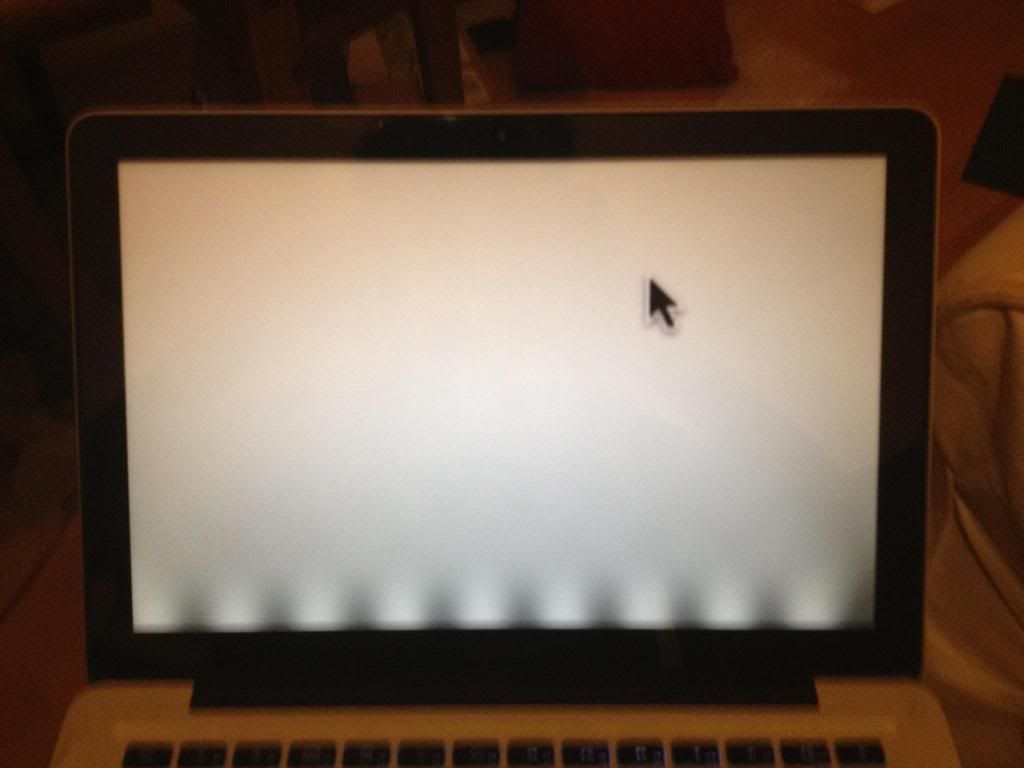
Well, my display ended up looking like this after the repair:
http://i1106.photobucket.com/albums/h366...
As you can see, there was a light/dark banded pattern along the bottom of the screen, corresponding to the LCD's backlight. In my case it was also accompanied by a constant high pitched whistling noise. I swear to anything that's holy, it was not coming from the fan or the speaker, but rather the motherboard itself.
Anyway, both these problems went away when I disconnected and reconnected the connector at this stage. I'm saying this on the off chance it helps someone else.
It's not to clear but there is a piece of spring steel that rotates away from the main (circuit board side) of the connector....this piece sort of hugs the parameter of the screen cable locking it to the circuit board...both arms wrapped around your brother....looking closely (10x magnifier) at this cable one of the gold connections is slightly oxidized---my display arbitrarily flickers and this symptom is lessened as the temperature increases...I suspect this is the cuase of the screen flashing on/off
-
-
-
-
上部ケースに留められた2つのディスプレイブラケットから 6.5 mm外付けトルクスネジを2本ずつ(計4本)を外します。
-
Mid 2009モデルはT6トルクスドライバーが必要です。一方でMid 2010モデルはT8ドライバーが必要です。
Hey folks, regarding the screw/driver sizes: there are separate guides for the Mid 2010 model with the T8 screws. Always use the correct guide for your model to avoid confusion, stripped screws, etc. Hope this helps!
-
-
-
上部ケースに留めれらたディスプレイから最後の残りの6 mm トルクスネジを外します。
Removing the screen assembly this way, with the computer standing on edge, is needlessly risky and difficult. By the 5th or 6th time I did this procedure (of perhaps a hundred), it dawned on me that there’s a way, way easier method for the whole lid removal job: 1. After removing the bottom cover and disconnecting power, hang the open laptop, keyboard down, facing away, over the edge of your work table with the lid assembly hanging down, monitor facing toward the table and pushed against the table edge. (If you’re klutzy, tape the main body to the table so it can’t slide around.) 2. With the unit positioned this way, you can easily disconnect the various cables & remove the 6 hinge screws. Now the lid assembly will just be hanging, easy to lift away from the main body without difficulty or danger. 3. Reverse this to put it back together.
Nice tip, Clinton! I’ll have to try that next time. Do you have photos of how it is done so this guide can be updated?
hackerb9 -
-
-
-
ブラケットやケーブルが絡まないように気をつけながら、上部ケースからディスプレイを持ち上げて外します。
May be in the wrong place but then please direct me. At this step, can I just take off the upper half (meaning the screen, LCD, and top housing shell in one) and simply replace it with another upper half of the same edition???
Yes, you can. Thanks what I'm doing now. :)
-
-
-
画像にあるようにクラッチカバーを手に取り、ディスプレイの右側に向けてスライドします。
i've found this impossible to get back on correctly.
i cant get the plastic to slide back that 1/4" it needs to fit properly
Does anyone know any tricks? :(
I was replacing a clutch cover that had cracked into a few pieces. I found the replacement didn’t slide to the left on installation. On further investigation I found the tabs from the old one were broken off inside where the cover slides. Once they were removed the install wen much better.
I found my replacement cover on Amazon.ca in case someone needs a Canadian source.
-
-
-
ディスプレイからクラッチカバーを取り出します。
The flat face goes on the bottom edge of the display. The display and wifi cables must be routed below the hinges in the display, that is, closer to the bottom edge of the display.
-
-
-
ディスプレイにカメラケーブルのリテイナーを固定している3.3 mmプラスネジを1本外します。
this is on the other side, watch the glass of the display below
Thank you! I thought the photo was looking at the left hand side.
-
-
-
画像のようにディスプレイの方向を変えて、黒色のプラスチックカメラケーブルのリテイナーをディスプレイの右側に向けて引っ張ります。
-
カメラケーブルのリテイナーを取り出します。
In the second picture for this step the U notches on the wifi connector are facing out when in the socket, and this is quite misleading. Putting them in like this will not work and could potentially cause some serious damage to wifi card or motherboard. Be wary of this guide, and make sure you take pictures of how things are before you touch them.
Sorprende como reparar mac fácil y rápido -
-
-
カメラケーブルのコネクタをディスプレイの右側に向けてゆっくりと引っ張り、AirPortカード上のソケットから引き抜きます。
I fried both of my Airport cards, couldn't figure out why, and came back here and read about these little U-shaped notches. I had to bring the computer into my office to compare both sides of this cable. I would be nice to make sure that this tid bit of information is very noticeable for those who are following along.
Yea, I fried two motherboards before I came back here and re-read that the U notches must face the airport card.
wcking -
A super closeup photo of these notches would very helpful.
Peter Mayo - 返信
If the note in this step can be updated to more accurately describe why the notches must be visible, that would be most helpful.
Perhaps written as per “The camera cable (ie the AirPort cable) whilst it can fit in both ways, you WILL cause damage to either the card, the motherboard or both if the orientation is not correct.
The cable MUST be installed so that the notches on one side of the cable are not visible”
Er, how sure is everyone about the directionality here? In the various images in this tutorial the connector appears with the U notches both facing and away. Perhaps the images reflect the learning process, but maybe the dot on the cable is key? One thing I can confirm is that it does matter - the cable connectivity is not symmetric.
Well, I don't yet know what damage I did to my logic board, but the instructions here are correct, at least for the system I am working with: if installed the other way around (with the U notches facing away from the connector), the system will turn on but when you try to shut it off (power button, shutdown option in OS) it will immediately turn back on. Only a long-press on the power button will shut the system down such that it stays off.
-
-
-
AirPortカード横と右側クラッチの蝶番を固定している残りの3 mmプラスネジを外します。
This photo can be slightly misleading if you're not careful. It appears that unlike my cable, the pictured cable has the gray dot on both sides. In this photo you can see the 2 little sideways U notches that should be on the OTHER side. In photo 22 you can see that there are NO such notches as he is sliding the cable out of the connector.
My gray dot is only on the underside (not visible when the cable is plugged in correctly. When I first took the cable out to replace my Airport board, I thought maybe it had been inserted the wrong way which will damage the motherboard. So the gray dots are not a good indicator, just look for the sideways U notches as indicated in the iFixit directions.
-


デバイスを再組み立てする際は、これらのインストラクションを逆の順番に従って作業を進めてください。
デバイスを再組み立てする際は、これらのインストラクションを逆の順番に従って作業を進めてください。
81 の人々がこのガイドを完成させました。
以下の翻訳者の皆さんにお礼を申し上げます:
100%

Midori Doiさんは世界中で修理する私たちを助けてくれています! あなたも貢献してみませんか?
翻訳を始める ›

5 件のコメント
Hello,
Andrew ...my salute to you. This just worked fine to fix my wifi hardware not installed problem on my Macbook pro (2010 mid). Thank you very much.
Regards,
Abhi
Very good instruction, but I still get „No hardware installed“. Any way to exchange the cable between Airport card and logic board? I‘m afraid no.
I have this problem
Luego de instalar el wifi card sigo teniendo el aviso de no hardware instalado. Cuál es la causa y que debo hacer ?
Compare the short screws carefully before reinstalling them. The shouldered screws go in the holes on the front edge.
David Kilbridge - 返信
Before I started removing any screws I took a piece of paper and drew the bottom of the laptop and put a piece of double-sided tape in the spot where each screw goes. That way when I took out the screws, I could put them on the tape so I knew exactly which screw went in which spot. I did the same thing for dismantling the inside on another sheet of paper, then a third sheet for the screen after getting the front glass off.
mastover - 返信
I use a similar technique: I print out the iFixit manual for the job, and Scotch-tape down the screws/brackets/cables I remove at each step next to the component descriptions. That way, when I'm reassembling, the bits are taped right next to the photo of where they came from.
adlerpe -
That's exactly what I do for all my repairs! It's the best way to keep track of all of the parts ' original location and to make sure that you don't miss any parts during reassembly.
joyitsjennie -
Great idea and one I use often
Thomas Overstreet -
Excellent idea! Thanks for sharing it here.
Laura Sharkey -
I used a 00 that fit but the screws were very tight so I used a tiny paintbrush with some wd40 on it and put it around the edges of the screws. Worked like a charm
valentinedhdh - 返信
I use a magnetic mat and place the screws in order on that :)
Cary B - 返信