メインコンテンツにスキップ

このバージョンは誤った内容を含んでいる可能性があります。最新の承認済みスナップショットに切り替えてください。

必要な工具と部品

  1. , 下部ケース: 手順 1、 1の画像 1
    • 次のネジを10本外します。

    • 14.4 mm #00プラスネジー3本

    • 3.5 mm #00プラスネジー3本

    • 3.5 mm #00 肩付きプラスネジー4本

    • 小さなネジを交換する際は、ケースのわずかに湾曲した部分に対し、垂直にネジを揃えてください。

  2. : 手順 2、 2の画像 1 : 手順 2、 2の画像 2
    • 排気口(液晶ヒンジ部)付近より、底ケースを指で開けます。

    • 底ケースを取り外します。

  3. , バッテリーの接続: 手順 3、 2の画像 1 , バッテリーの接続: 手順 3、 2の画像 2
    • スパッジャーの先端を使って、バッテリーコネクターをロジックボードのソケットから上向きに引き上げます。

    • ソケットからバッテリーコネクターを外す際に、両側の短いサイドから上向きに引き上げると作業がしやすいです。コネクターの角に気をつけてください。簡単に壊れてしまいます。

  4. : 手順 4、 1の画像 1
    • バッテリーケーブルをロジックボード上のソケットから外して、わずかに折り曲げておきます。そうすると、作業中にアクシデントで接続することがありません。

  5. , ファン: 手順 5、 3の画像 1 , ファン: 手順 5、 3の画像 2 , ファン: 手順 5、 3の画像 3
    • スパッジャーの先端を使って、ロジックボード上のソケットからファンコネクターを持ち上げます。

    • コネクターの接続を緩めるために、ファンケーブルファイヤーの下からスパッジャーをひねりながら作業を進めてください。

    • ファンソケットとファンコネクターは2、3番目の画像で確認できます。プラスチック製のファンソケットをロジックボードから外す際に壊さないようご注意ください。スパッジャーを使って、ファンコネクターをソケットからまっすぐ持ち上げます。2番目の画像はロジックボードのレイアウトです。お持ちのデバイスと若干異なる部分があるかもしれませんが、ファンソケットは同一のはずです。

  6. : 手順 6、 1の画像 1
    • ロジックボードに留められたファンから次の3本のネジを外します。

    • 7.2 mm T6 トルクスネジー1本

    • 5.3 mm T6 トルクスネジー2本

  7. : 手順 7、 1の画像 1
    • ケーブルが絡まないように注意しながら、ロジックボードの角からファンを持ち上げます。

  8. , ロジックボード: 手順 8、 2の画像 1 , ロジックボード: 手順 8、 2の画像 2
    • スパッジャーの先端を使って、右側スピーカー/サブウーファーケーブルを上部ケースに装着された固定フィンガーの下から持ち上げます。

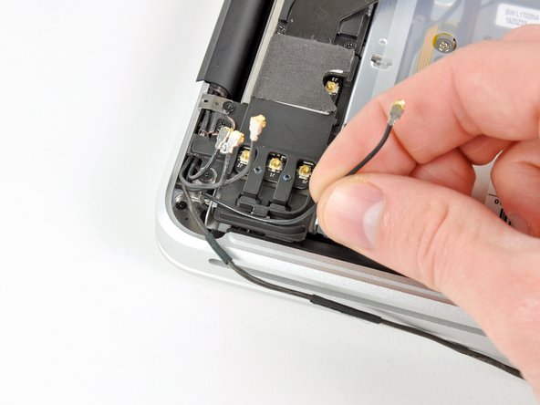
    • 右側のスピーカー/サブウーファーケーブルをロジックボード上のソケットからコネクターを持ち上げるため、上向きに引っ張ります。

  9. : 手順 9、 1の画像 1
    • ロジックボードからカメラケーブルの接続を外します。

    • ロジックボードの表面に対して平行になるようにケーブルを引っ張ります。ケーブルを上向きに引っ張るとロジックボードやケーブル自体にダメージを与えてしまうことがあります。

  10. : 手順 10、 2の画像 1 : 手順 10、 2の画像 2
    • 次の4本のケーブルの接続を外します。

    • AirPort/Bluetoothケーブル

    • 光学ドライブケーブル

    • ハードドライブケーブル

    • トラックパッドケーブル

    • ケーブルの接続を外すには、スパッジャーの平面側先端を使って、ロジックボード上のソケットからコネクターを引き上げます。

  11. : 手順 11、 3の画像 1 : 手順 11、 3の画像 2 : 手順 11、 3の画像 3
    • 指の爪を使って、キーボードリボンケーブルのZIFソケット上にある固定フラップを引き上げます。

    • 丁番型の固定フラップのみを引き上げます。ソケット自体には接触しないでください。

    • スパッジャーの先端を使って、ソケットからキーボードリボンケーブルを持ち上げます。

    • ケーブルを挿入しにくいかもしれません。作業が難しい場合は、一時的にテープをケーブルに貼り付けて、ソケットに挿入しやすくします。

  12. : 手順 12、 1の画像 1
    • もし対応する場合は、キーボードのバックライトケーブルソケットを覆っている黒色のテープを取り外します。

  13. : 手順 13、 3の画像 1 : 手順 13、 3の画像 2 : 手順 13、 3の画像 3
    • スパッジャーの先端か指の爪を使って、キーボードバックライトリボンケーブルのZIFソケット上にある固定フラップを返します。

    • 丁番型の固定フラップのみを持ち上げてください。ソケット自体には接触しないでください。

    • ソケットからキーボードバックライトリボンケーブルを引き上げます。

  14. : 手順 14、 1の画像 1
    • スパッジャーの平面側先端を使って、スリープセンサー/バッテリー残量コネクターをロジックボード上のソケットから引き上げます。

  15. : 手順 15、 3の画像 1 : 手順 15、 3の画像 2 : 手順 15、 3の画像 3
    • ディスプレイデータケーブルロックに留められたプラスチック製のプルタブを掴み、コンピューターの DC-In側に向かって回します。

    • ロジックボード上のソケットからディスプレイデータケーブルを持ち上げます。

    • ディスプレイデータケーブルを持ち上げないでください。このソケットはとても壊れやすいです。ケーブルをロジックボードの表面に対して平行に引っ張ります。

  16. : 手順 16、 1の画像 1
    • 次の9本のネジを外します。

    • 3.6 mm T6トルクスネジ−5本

    • 4.3 mm T6トルクスネジー2本

    • 7.2 mm T6トルクスネジー2本

    • モデルによっては、次のようにネジが若干短い場合があります、

    • 3.0mmT6ネジー5本

    • 3.6mm T6ネジー2本

    • 6.7mm T6ネジー2本

  17. : 手順 17、 2の画像 1 : 手順 17、 2の画像 2
    • 次のネジを2本外します。

    • 8.6 mmプラスネジー1本

    • 5.5 mmプラスネジー1本

    • 上部ケースからディスプレイデータケーブルリテーナを取り出します。

  18. : 手順 18、 1の画像 1
    • スパッジャーの先端を使って、上部ケースに付けられた接着剤をマイクから丁寧に剥がしていきます。

  19. : 手順 19、 1の画像 1
    • コネクターに注意しながら、光学ドライブ付近の端からロジックボードを持ち上げます。

    • ボードを曲げないで、上部ケースに挟まれているDC-In ボードへの可動性連結に注意しながら上部ケースからロジックボードを抜き出します。

    • ロジックボードを取り出します。

  20. この手順は未翻訳です。 翻訳を手伝う。

    : 手順 20、 1の画像 1
    • Remove the following two screws:

    • One 5.6 mm Tri-point screw

    • One 13 mm Tri-point screw

  21. この手順は未翻訳です。 翻訳を手伝う。

    : 手順 21、 1の画像 1
    • Carefully peel the battery warning label off the upper case between the battery and the optical drive.

    • Do not remove the label from the battery.

  22. この手順は未翻訳です。 翻訳を手伝う。

    : 手順 22、 1の画像 1
    • Use the attached plastic pull tab to help remove the battery from the upper case.

  23. この手順は未翻訳です。 翻訳を手伝う。

    : 手順 23、 2の画像 1 : 手順 23、 2の画像 2
    • Remove the two Phillips screws securing the hard drive bracket to the upper case.

    • These screws will remain captive to the hard drive bracket.

    • Remove the hard drive bracket.

    • The hard drive bracket may be firmly seated against the upper case.

  24. この手順は未翻訳です。 翻訳を手伝う。

    : 手順 24、 3の画像 1 : 手順 24、 3の画像 2 : 手順 24、 3の画像 3
    • Use the attached pull tab to lift the hard drive out of the upper case.

    • Pull the hard drive cable away from the body of the hard drive.

    • Remove the hard drive.

  25. この手順は未翻訳です。 翻訳を手伝う。

    : 手順 25、 1の画像 1
    • Remove the following four screws:

    • Two 3 mm Phillips screws

    • Two 9.7 mm Phillips screws

  26. この手順は未翻訳です。 翻訳を手伝う。

    : 手順 26、 1の画像 1
    • Carefully peel up the thin IR sensor/sleep LED ribbon cable from the adhesive securing it to the upper case.

  27. この手順は未翻訳です。 翻訳を手伝う。

    : 手順 27、 2の画像 1 : 手順 27、 2の画像 2
    • Pull the front hard drive bracket containing the IR sensor/sleep LED away from the front edge of the upper case.

    • Remove the hard drive cable.

  28. この手順は未翻訳です。 翻訳を手伝う。

    : 手順 28、 1の画像 1
    • Carefully move the AirPort/Bluetooth ribbon cable out of the way as you peel the camera cable off the adhesive securing it to the subwoofer and the AirPort/Bluetooth bracket.

    • De-route the camera cable out from under the retaining finger molded into the AirPort/Bluetooth bracket.

  29. この手順は未翻訳です。 翻訳を手伝う。

    : 手順 29、 3の画像 1 : 手順 29、 3の画像 2 : 手順 29、 3の画像 3
    • Disconnect the four antenna connectors boxed in red in the first picture.

    • To do so, use the tip of a spudger to pry their connectors up from the sockets on the AirPort/Bluetooth board.

    • De-route each of the cables from their channels in the AirPort/Bluetooth bracket.

  30. この手順は未翻訳です。 翻訳を手伝う。

    : 手順 30、 1の画像 1
    • Remove the following five screws:

    • Two 10.3 mm Phillips screws

    • Two 3.1 mm Phillips screws

    • One 5 mm Phillips screw

  31. この手順は未翻訳です。 翻訳を手伝う。

    : 手順 31、 2の画像 1 : 手順 31、 2の画像 2
    • Pull the AirPort/Bluetooth assembly and the Subwoofer upward near the center of the side of the optical drive until they clear each other.

    • Remove the AirPort/Bluetooth board assembly.

  32. この手順は未翻訳です。 翻訳を手伝う。

    : 手順 32、 1の画像 1
    • Remove the three 2.7 mm Phillips screws securing the optical drive to the upper case.

  33. この手順は未翻訳です。 翻訳を手伝う。

    : 手順 33、 1の画像 1
    • Lift the optical drive from the edge nearest the display and remove it from the upper case.

  34. この手順は未翻訳です。 翻訳を手伝う。

    : 手順 34、 1の画像 1
    • Peel the right speaker cable off the upper case.

  35. この手順は未翻訳です。 翻訳を手伝う。

    : 手順 35、 2の画像 1 : 手順 35、 2の画像 2
    • Use a plastic opening tool or another thin prying object to carefully pry the right speaker up from the adhesive securing it to the upper case.

    • Start prying up from the edge of the right speaker nearest the display. Starting from the other side may damage one of the antennas.

    • Pry up along the edge of the right speaker until it is separated from the upper case.

  36. この手順は未翻訳です。 翻訳を手伝う。

    : 手順 36、 1の画像 1
    • Pull the right speaker out from under the optical drive opening.

  37. この手順は未翻訳です。 翻訳を手伝う。

    : 手順 37、 1の画像 1
    • Remove two of the three 6 mm T8 Torx screws securing the right side of the display to the upper case.

    • We purposely have you leave one screw attaching the display to the upper case to aid in future steps.

  38. この手順は未翻訳です。 翻訳を手伝う。

    : 手順 38、 1の画像 1
    • Remove the small piece of foam tape covering the left display hinge screws.

  39. この手順は未翻訳です。 翻訳を手伝う。

    : 手順 39、 1の画像 1
    • Remove two of the three 6 mm T8 Torx screws securing the left side of the display to the upper case.

    • We purposely have you leave one screw attaching the display to the upper case to aid in future steps.

  40. この手順は未翻訳です。 翻訳を手伝う。

    : 手順 40、 1の画像 1
    • Open your MacBook Pro so the display is perpendicular to the upper case.

    • Place your opened MacBook Pro on a table as pictured.

    • While holding the display and upper case together with your left hand, remove the remaining T8 Torx screw from the lower display bracket.

  41. この手順は未翻訳です。 翻訳を手伝う。

    : 手順 41、 1の画像 1
    • Be sure to hold the display and upper case together with your left hand. Failure to do so may cause the freed display/upper case to fall, potentially damaging each component.

    • Remove the last remaining T8 Torx screw securing the display to the upper case.

  42. この手順は未翻訳です。 翻訳を手伝う。

    : 手順 42、 3の画像 1 : 手順 42、 3の画像 2 : 手順 42、 3の画像 3
    • Grab the upper case with your right hand and rotate it slightly toward the top of the display so the upper display bracket clears the edge of the upper case.

    • Rotate the display slightly away from the upper case.

    • Lift the display up and away from the upper case, minding any brackets or cables that may get caught.

    • Upper case remains.

  43. : 手順 43、 1の画像 1
    • 赤でハイライトされた1.2mmプラスネジを4本外します。

  44. この手順は未翻訳です。 翻訳を手伝う。

    : 手順 44、 1の画像 1
    • Carefully dislodge the edge of the trackpad closest to the keyboard from its recess in the upper case by pushing it away from the brackets attached to the upper case.

    • De-route the trackpad cable through its slot cut into the upper case.

  45. : 手順 45、 1の画像 1
    • 上部ケースの外縁からトラックパッドを引き離します。

    • トラックパッドを取り外し、脇に置きます。

  46. この手順は未翻訳です。 翻訳を手伝う。

    : 手順 46、 1の画像 1
    • In the following steps, you will be working on your new upper case.

    • Use a T6 Torx screwdriver to loosely install the 1.1 mm set screw included with your new upper case into its tapped hole near the middle of the trackpad opening on your new upper case.

    • Only tighten it about one turn for now.

  47. この手順は未翻訳です。 翻訳を手伝う。

    : 手順 47、 2の画像 1 : 手順 47、 2の画像 2
    • Carefully insert the cable from your old trackpad through its slot cut into your new upper case.

    • Use one hand to hold the trackpad cable in place as you insert the two retaining tabs on the outer edge of the trackpad under the lip on the upper case.

    • Pull the trackpad cable as you seat the trackpad into its void in your new upper case.

  48. この手順は未翻訳です。 翻訳を手伝う。

    : 手順 48、 1の画像 1
    • Insert a 1.2 mm Phillips screw into each of the outer holes drilled into the trackpad (two screws total).

    • You'll install the rest in a bit.

    • Tighten the screws, then back them out about a quarter turn to aid in aligning your trackpad during the next few steps.

  49. : 手順 49、 1の画像 1
    • トラックパッドをクリックしようとし続けながら、カチッという音が工場出荷時の「感触」に戻るまでT6トルクス止めネジを慎重に締めます。

    • トラックパッドのカチッという音によって、ネジがきちんと締まっていることがわかります。止めネジが緩すぎると、カチッという音がする前にトラックパッドに遊びがあります。きつすぎると、トラックパッドはあまりにも容易にクリックできてしまうので、特徴的なマウスのクリックノイズが大きくなりません。

  50. この手順は未翻訳です。 翻訳を手伝う。

    : 手順 50、 1の画像 1
    • Next, flip your upper case over so the keyboard side is facing up.

    • Align the trackpad so it is centered in its hole cut into the upper case.

  51. この手順は未翻訳です。 翻訳を手伝う。

    : 手順 51、 1の画像 1
    • Tighten the outer two screws along the inner edge of the trackpad and check the alignment of it on the outer side of the upper case.

    • If its alignment looks good, install the rest of the Phillips screws along the inner edge of the trackpad.

    • Before reassembling your machine, verify that the set screw is still installed in a position so the mouse will click correctly.

ゴール

78 の人々がこのガイドを完成させました。

作成者

5人の作成者と共同で作成されました。

Andrew Bookholt

586,221 ポイント

619のガイドは作成済み

3 件のコメント

Great stuff. I could replace a keyboard in my son's MBP (2011) without any problem. However, later I found the laptop not going to sleep when the lid is closed. Moving a small magnet around the screen bezel does the trick. I found the sleep sensor/battery indicator connector broken. I also replaced that but the problem persists. I must also add that I could replace a wifi card in a friends Macbook Air. Thank you very much for these documents and the pictorial guide.

Durga Mahapatra - 返信

I am currently typing on my repaired macbook pro, it took awhile and the a-stock replacement case had a few problems like missing foam bits, metal spacers, the electrical part under the disk drive opening and a broken off screw in one of the two power button locations but with some careful removal of the items from the old case and placement with a bit of superglue in the purchased case, it all went back together. And works which is what counts. It was a mid 2011 that suffered a coffee spill when only 2 months old put away until now. (in other words the new used case had been stripped clean which should be mentioned in the sales description) Otherwise a great instructional guide.

Jordan Nygaard - 返信

Great walk-thru. Be sure to check out the step’s comments. Many tips are there, especially for the reassembly. Some tricks there help. Be sure to check the comments on the keyboard ribbon. The tape trick is the only way I think you will get it back in that slot.

Lee Hughart - 返信

コメントを追加

統計データ:

過去 24時間: 3

過去 7 日: 17

過去 30 日: 87

今までの合計 99,875