メインコンテンツにスキップ

このバージョンは誤った内容を含んでいる可能性があります。最新の承認済みスナップショットに切り替えてください。

必要条件のみ
この修理ガイドは、他のガイドの前提条件として使用されます。それ自体は不完全で、単独で使用されることはありません。

必要な工具と部品

  1. , 下部ケース: 手順 1、 1の画像 1
    • 次のネジを10本外します。

    • 14.4 mm #00プラスネジー3本

    • 3.5 mm #00プラスネジー3本

    • 3.5 mm #00 肩付きプラスネジー4本

    • 小さなネジを交換する際は、ケースのわずかに湾曲した部分に対し、垂直にネジを揃えてください。

  2. : 手順 2、 2の画像 1 : 手順 2、 2の画像 2
    • 排気口(液晶ヒンジ部)付近より、底ケースを指で開けます。

    • 底ケースを取り外します。

  3. , バッテリーの接続: 手順 3、 2の画像 1 , バッテリーの接続: 手順 3、 2の画像 2
    • スパッジャーの先端を使って、バッテリーコネクターをロジックボードのソケットから上向きに引き上げます。

    • ソケットからバッテリーコネクターを外す際に、両側の短いサイドから上向きに引き上げると作業がしやすいです。コネクターの角に気をつけてください。簡単に壊れてしまいます。

  4. : 手順 4、 1の画像 1
    • バッテリーケーブルをロジックボード上のソケットから外して、わずかに折り曲げておきます。そうすると、作業中にアクシデントで接続することがありません。

  5. , ファン: 手順 5、 3の画像 1 , ファン: 手順 5、 3の画像 2 , ファン: 手順 5、 3の画像 3
    • スパッジャーの先端を使って、ロジックボード上のソケットからファンコネクターを持ち上げます。

    • コネクターの接続を緩めるために、ファンケーブルファイヤーの下からスパッジャーをひねりながら作業を進めてください。

    • ファンソケットとファンコネクターは2、3番目の画像で確認できます。プラスチック製のファンソケットをロジックボードから外す際に壊さないようご注意ください。スパッジャーを使って、ファンコネクターをソケットからまっすぐ持ち上げます。2番目の画像はロジックボードのレイアウトです。お持ちのデバイスと若干異なる部分があるかもしれませんが、ファンソケットは同一のはずです。

  6. : 手順 6、 1の画像 1
    • ロジックボードに留められたファンから次の3本のネジを外します。

    • 7.2 mm T6 トルクスネジー1本

    • 5.3 mm T6 トルクスネジー2本

  7. : 手順 7、 1の画像 1
    • ケーブルが絡まないように注意しながら、ロジックボードの角からファンを持ち上げます。

  8. , ロジックボード: 手順 8、 2の画像 1 , ロジックボード: 手順 8、 2の画像 2
    • スパッジャーの先端を使って、右側スピーカー/サブウーファーケーブルを上部ケースに装着された固定フィンガーの下から持ち上げます。

    • 右側のスピーカー/サブウーファーケーブルをロジックボード上のソケットからコネクターを持ち上げるため、上向きに引っ張ります。

  9. : 手順 9、 1の画像 1
    • ロジックボードからカメラケーブルの接続を外します。

    • ロジックボードの表面に対して平行になるようにケーブルを引っ張ります。ケーブルを上向きに引っ張るとロジックボードやケーブル自体にダメージを与えてしまうことがあります。

  10. : 手順 10、 2の画像 1 : 手順 10、 2の画像 2
    • 次の4本のケーブルの接続を外します。

    • AirPort/Bluetoothケーブル

    • 光学ドライブケーブル

    • ハードドライブケーブル

    • トラックパッドケーブル

    • ケーブルの接続を外すには、スパッジャーの平面側先端を使って、ロジックボード上のソケットからコネクターを引き上げます。

  11. : 手順 11、 3の画像 1 : 手順 11、 3の画像 2 : 手順 11、 3の画像 3
    • 指の爪を使って、キーボードリボンケーブルのZIFソケット上にある固定フラップを引き上げます。

    • 丁番型の固定フラップのみを引き上げます。ソケット自体には接触しないでください。

    • スパッジャーの先端を使って、ソケットからキーボードリボンケーブルを持ち上げます。

    • ケーブルを挿入しにくいかもしれません。作業が難しい場合は、一時的にテープをケーブルに貼り付けて、ソケットに挿入しやすくします。

  12. : 手順 12、 1の画像 1
    • もし対応する場合は、キーボードのバックライトケーブルソケットを覆っている黒色のテープを取り外します。

  13. : 手順 13、 3の画像 1 : 手順 13、 3の画像 2 : 手順 13、 3の画像 3
    • スパッジャーの先端か指の爪を使って、キーボードバックライトリボンケーブルのZIFソケット上にある固定フラップを返します。

    • 丁番型の固定フラップのみを持ち上げてください。ソケット自体には接触しないでください。

    • ソケットからキーボードバックライトリボンケーブルを引き上げます。

  14. : 手順 14、 1の画像 1
    • スパッジャーの平面側先端を使って、スリープセンサー/バッテリー残量コネクターをロジックボード上のソケットから引き上げます。

  15. : 手順 15、 3の画像 1 : 手順 15、 3の画像 2 : 手順 15、 3の画像 3
    • ディスプレイデータケーブルロックに留められたプラスチック製のプルタブを掴み、コンピューターの DC-In側に向かって回します。

    • ロジックボード上のソケットからディスプレイデータケーブルを持ち上げます。

    • ディスプレイデータケーブルを持ち上げないでください。このソケットはとても壊れやすいです。ケーブルをロジックボードの表面に対して平行に引っ張ります。

  16. : 手順 16、 1の画像 1
    • 次の9本のネジを外します。

    • 3.6 mm T6トルクスネジ−5本

    • 4.3 mm T6トルクスネジー2本

    • 7.2 mm T6トルクスネジー2本

    • モデルによっては、次のようにネジが若干短い場合があります、

    • 3.0mmT6ネジー5本

    • 3.6mm T6ネジー2本

    • 6.7mm T6ネジー2本

  17. : 手順 17、 2の画像 1 : 手順 17、 2の画像 2
    • 次のネジを2本外します。

    • 8.6 mmプラスネジー1本

    • 5.5 mmプラスネジー1本

    • 上部ケースからディスプレイデータケーブルリテーナを取り出します。

  18. : 手順 18、 1の画像 1
    • スパッジャーの先端を使って、上部ケースに付けられた接着剤をマイクから丁寧に剥がしていきます。

  19. : 手順 19、 1の画像 1
    • コネクターに注意しながら、光学ドライブ付近の端からロジックボードを持ち上げます。

    • ボードを曲げないで、上部ケースに挟まれているDC-In ボードへの可動性連結に注意しながら上部ケースからロジックボードを抜き出します。

    • ロジックボードを取り出します。

  20. この手順は未翻訳です。 翻訳を手伝う。

    : 手順 20、 1の画像 1
    • Remove the following two screws:

    • One 5.6 mm Tri-point screw

    • One 13 mm Tri-point screw

  21. この手順は未翻訳です。 翻訳を手伝う。

    : 手順 21、 1の画像 1
    • Carefully peel the battery warning label off the upper case between the battery and the optical drive.

    • Do not remove the label from the battery.

  22. この手順は未翻訳です。 翻訳を手伝う。

    : 手順 22、 1の画像 1
    • Use the attached plastic pull tab to help remove the battery from the upper case.

  23. この手順は未翻訳です。 翻訳を手伝う。

    : 手順 23、 2の画像 1 : 手順 23、 2の画像 2
    • Remove the two Phillips screws securing the hard drive bracket to the upper case.

    • These screws will remain captive to the hard drive bracket.

    • Remove the hard drive bracket.

    • The hard drive bracket may be firmly seated against the upper case.

  24. この手順は未翻訳です。 翻訳を手伝う。

    : 手順 24、 3の画像 1 : 手順 24、 3の画像 2 : 手順 24、 3の画像 3
    • Use the attached pull tab to lift the hard drive out of the upper case.

    • Pull the hard drive cable away from the body of the hard drive.

    • Remove the hard drive.

  25. この手順は未翻訳です。 翻訳を手伝う。

    : 手順 25、 1の画像 1
    • Remove the following four screws:

    • Two 3 mm Phillips screws

    • Two 9.7 mm Phillips screws

  26. この手順は未翻訳です。 翻訳を手伝う。

    : 手順 26、 1の画像 1
    • Carefully peel up the thin IR sensor/sleep LED ribbon cable from the adhesive securing it to the upper case.

  27. この手順は未翻訳です。 翻訳を手伝う。

    : 手順 27、 2の画像 1 : 手順 27、 2の画像 2
    • Pull the front hard drive bracket containing the IR sensor/sleep LED away from the front edge of the upper case.

    • Remove the hard drive cable.

  28. この手順は未翻訳です。 翻訳を手伝う。

    : 手順 28、 1の画像 1
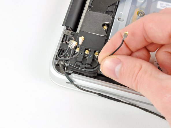
    • Carefully move the AirPort/Bluetooth ribbon cable out of the way as you peel the camera cable off the adhesive securing it to the subwoofer and the AirPort/Bluetooth bracket.

    • De-route the camera cable out from under the retaining finger molded into the AirPort/Bluetooth bracket.

  29. この手順は未翻訳です。 翻訳を手伝う。

    : 手順 29、 3の画像 1 : 手順 29、 3の画像 2 : 手順 29、 3の画像 3
    • Disconnect the four antenna connectors boxed in red in the first picture.

    • To do so, use the tip of a spudger to pry their connectors up from the sockets on the AirPort/Bluetooth board.

    • De-route each of the cables from their channels in the AirPort/Bluetooth bracket.

  30. この手順は未翻訳です。 翻訳を手伝う。

    : 手順 30、 1の画像 1
    • Remove the following five screws:

    • Two 10.3 mm Phillips screws

    • Two 3.1 mm Phillips screws

    • One 5 mm Phillips screw

  31. この手順は未翻訳です。 翻訳を手伝う。

    : 手順 31、 2の画像 1 : 手順 31、 2の画像 2
    • Pull the AirPort/Bluetooth assembly and the Subwoofer upward near the center of the side of the optical drive until they clear each other.

    • Remove the AirPort/Bluetooth board assembly.

  32. この手順は未翻訳です。 翻訳を手伝う。

    : 手順 32、 1の画像 1
    • Remove the three 2.7 mm Phillips screws securing the optical drive to the upper case.

  33. この手順は未翻訳です。 翻訳を手伝う。

    : 手順 33、 1の画像 1
    • Lift the optical drive from the edge nearest the display and remove it from the upper case.

  34. この手順は未翻訳です。 翻訳を手伝う。

    : 手順 34、 1の画像 1
    • Peel the right speaker cable off the upper case.

  35. この手順は未翻訳です。 翻訳を手伝う。

    : 手順 35、 2の画像 1 : 手順 35、 2の画像 2
    • Use a plastic opening tool or another thin prying object to carefully pry the right speaker up from the adhesive securing it to the upper case.

    • Start prying up from the edge of the right speaker nearest the display. Starting from the other side may damage one of the antennas.

    • Pry up along the edge of the right speaker until it is separated from the upper case.

  36. この手順は未翻訳です。 翻訳を手伝う。

    : 手順 36、 1の画像 1
    • Pull the right speaker out from under the optical drive opening.

  37. この手順は未翻訳です。 翻訳を手伝う。

    : 手順 37、 1の画像 1
    • Remove two of the three 6 mm T8 Torx screws securing the right side of the display to the upper case.

    • We purposely have you leave one screw attaching the display to the upper case to aid in future steps.

  38. この手順は未翻訳です。 翻訳を手伝う。

    : 手順 38、 1の画像 1
    • Remove the small piece of foam tape covering the left display hinge screws.

  39. この手順は未翻訳です。 翻訳を手伝う。

    : 手順 39、 1の画像 1
    • Remove two of the three 6 mm T8 Torx screws securing the left side of the display to the upper case.

    • We purposely have you leave one screw attaching the display to the upper case to aid in future steps.

  40. この手順は未翻訳です。 翻訳を手伝う。

    : 手順 40、 1の画像 1
    • Open your MacBook Pro so the display is perpendicular to the upper case.

    • Place your opened MacBook Pro on a table as pictured.

    • While holding the display and upper case together with your left hand, remove the remaining T8 Torx screw from the lower display bracket.

  41. この手順は未翻訳です。 翻訳を手伝う。

    : 手順 41、 1の画像 1
    • Be sure to hold the display and upper case together with your left hand. Failure to do so may cause the freed display/upper case to fall, potentially damaging each component.

    • Remove the last remaining T8 Torx screw securing the display to the upper case.

  42. この手順は未翻訳です。 翻訳を手伝う。

    : 手順 42、 3の画像 1 : 手順 42、 3の画像 2 : 手順 42、 3の画像 3
    • Grab the upper case with your right hand and rotate it slightly toward the top of the display so the upper display bracket clears the edge of the upper case.

    • Rotate the display slightly away from the upper case.

    • Lift the display up and away from the upper case, minding any brackets or cables that may get caught.

    • Upper case remains.

ゴール

ある他の人がこのガイドを完成しました。

作成者

4人の作成者と共同で作成されました。

Andrew Bookholt

586,296 ポイント

619のガイドは作成済み

0 件のコメント

コメントを追加

統計データ:

過去 24時間: 0

過去 7 日: 0

過去 30 日: 0

今までの合計 5,899