メインコンテンツにスキップ

MacBook Pro 13" Retina Display Early 2013 Logic Board Replacement

必要な工具と部品

  1. MacBook Pro 13" Retina Display Early 2013 Logic Board Replacement, Lower Case: 手順 1、 1の画像 1
    この手順で使用する道具:
    Magnetic Project Mat
    $19.95
    購入する
    • Remove the following ten screws securing the lower case to the upper case:

    • Two 2.3 mm P5 Pentalobe screws

    • Eight 3.0 mm P5 Pentalobe screws

    • Throughout this repair, keep track of each screw and make sure it goes back exactly where it came from to avoid damaging your device.

  2. MacBook Pro 13" Retina Display Early 2013 Logic Board Replacement: 手順 2、 1の画像 1
    • Wedge your fingers between the upper case and the lower case.

    • Gently pull the lower case away from the upper case.

    • Remove the lower case and set it aside.

  3. MacBook Pro 13" Retina Display Early 2013 Logic Board Replacement: 手順 3、 3の画像 1 MacBook Pro 13" Retina Display Early 2013 Logic Board Replacement: 手順 3、 3の画像 2 MacBook Pro 13" Retina Display Early 2013 Logic Board Replacement: 手順 3、 3の画像 3
    • During reassembly, gently push down the center of the lower case to reattach the two plastic clips.

    • The lower case is connected to the upper case at the center, with two plastic clips.

  4. MacBook Pro 13" Retina Display Early 2013 Logic Board Replacement, Battery Connector: 手順 4、 1の画像 1
    • Remove the plastic cover adhered to the battery contact board.

  5. MacBook Pro 13" Retina Display Early 2013 Logic Board Replacement: 手順 5、 1の画像 1
    • Remove the following screws securing the battery connector board to the logic board:

    • Two 2.8 mm T6 Torx screws

    • One 7.0 mm T6 Torx shouldered screw

  6. MacBook Pro 13" Retina Display Early 2013 Logic Board Replacement: 手順 6、 2の画像 1 MacBook Pro 13" Retina Display Early 2013 Logic Board Replacement: 手順 6、 2の画像 2
    • Use tweezers to remove the small plastic cover located near the bottom right of the battery connector board.

  7. MacBook Pro 13" Retina Display Early 2013 Logic Board Replacement: 手順 7、 1の画像 1
    • Remove the wide head 6.4 mm T6 Torx screw securing the battery connector to the logic board assembly.

  8. MacBook Pro 13" Retina Display Early 2013 Logic Board Replacement: 手順 8、 2の画像 1 MacBook Pro 13" Retina Display Early 2013 Logic Board Replacement: 手順 8、 2の画像 2
    • Carefully lift the battery connector board up off the logic board.

    • It is recommended to bend the battery cables just slightly, to keep the board suspended up above the logic board and out of the way.

    • Do not fold the board completely over, or crease the cables, as this may damage the battery.

  9. MacBook Pro 13" Retina Display Early 2013 Logic Board Replacement, Battery Contact Board: 手順 9、 2の画像 1 MacBook Pro 13" Retina Display Early 2013 Logic Board Replacement, Battery Contact Board: 手順 9、 2の画像 2
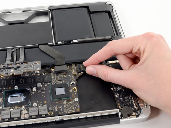
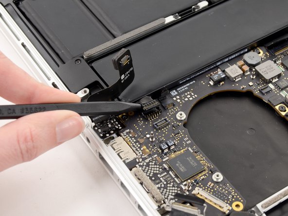
    • Grasp the Interposer with tweezers.

    • An interposer is the name for an interface that links one electrical connection to another. In this repair, it is the board connecting the battery to logic board.

    • Lift the Interposer off the logic board and remove it.

    • Removing this board will ensure that the battery remains disconnected throughout your repair, preventing your computer from accidentally powering on. It's also a good idea to take it out so it doesn't fall out unexpectedly.

  10. MacBook Pro 13" Retina Display Early 2013 Logic Board Replacement, Heat Sink Assembly: 手順 10、 1の画像 1
    • Remove the following screws securing the heat sink to the logic board assembly:

    • One 2.4 mm Phillips #00 screw

    • One 3.4 mm T5 Torx screw

    • Four 2.7 mm T5 Torx screws

  11. MacBook Pro 13" Retina Display Early 2013 Logic Board Replacement: 手順 11、 2の画像 1 MacBook Pro 13" Retina Display Early 2013 Logic Board Replacement: 手順 11、 2の画像 2
    • Lift and remove the heat sink up off the logic board assembly.

    • When reinstalling the heat sink, be sure to apply a new layer of thermal paste. If you have never applied thermal paste before, we have a guide that makes it easy.

  12. MacBook Pro 13" Retina Display Early 2013 Logic Board Replacement, I/O Board Data Cable: 手順 12、 2の画像 1 MacBook Pro 13" Retina Display Early 2013 Logic Board Replacement, I/O Board Data Cable: 手順 12、 2の画像 2
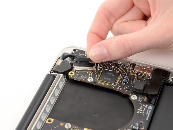
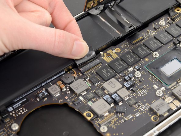
    • Use the flat end of a spudger to pry the right side of the I/O board data cable connector up off its socket on the I/O board.

    • When prying the I/O board data cable connector from its socket, make sure to pry the connector itself and not the socket. Prying the socket may cause irreversible damage to the I/O board.

  13. MacBook Pro 13" Retina Display Early 2013 Logic Board Replacement: 手順 13、 2の画像 1 MacBook Pro 13" Retina Display Early 2013 Logic Board Replacement: 手順 13、 2の画像 2
    • Wedge the flat end of a spudger beneath the left side of the I/O board data cable connector.

    • Gently twist the spudger to disconnect the I/O board data cable connector from its socket on the logic board.

  14. MacBook Pro 13" Retina Display Early 2013 Logic Board Replacement: 手順 14、 1の画像 1
    • Lift and remove the I/O board data cable from the MacBook Pro.

  15. MacBook Pro 13" Retina Display Early 2013 Logic Board Replacement, iSight Camera Cable: 手順 15、 2の画像 1 MacBook Pro 13" Retina Display Early 2013 Logic Board Replacement, iSight Camera Cable: 手順 15、 2の画像 2
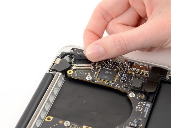
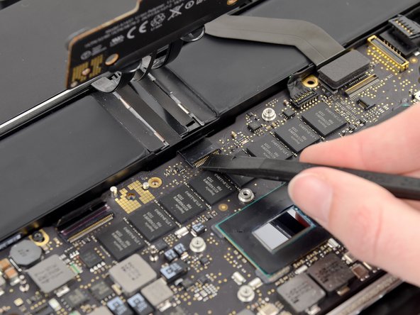
    • Use the tip of a spudger to push the iSight camera cable connector straight away from its socket on the logic board.

    • It is recommended to carefully push on both sides of the connector to "walk" it out of its socket.

  16. MacBook Pro 13" Retina Display Early 2013 Logic Board Replacement: 手順 16、 2の画像 1 MacBook Pro 13" Retina Display Early 2013 Logic Board Replacement: 手順 16、 2の画像 2
    • Move the iSight camera cable aside.

  17. MacBook Pro 13" Retina Display Early 2013 Logic Board Replacement, Right Fan: 手順 17、 3の画像 1 MacBook Pro 13" Retina Display Early 2013 Logic Board Replacement, Right Fan: 手順 17、 3の画像 2 MacBook Pro 13" Retina Display Early 2013 Logic Board Replacement, Right Fan: 手順 17、 3の画像 3
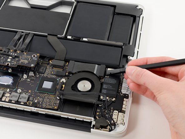
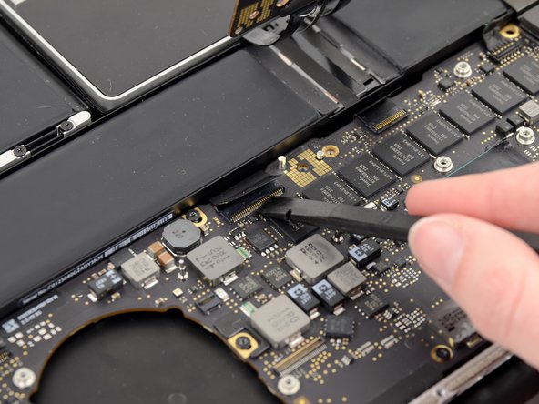
    • Use the tip of a spudger to flip up the retaining flap on the right fan ribbon cable ZIF socket.

    • Be sure you are prying up on the hinged retaining flap, not the socket itself.

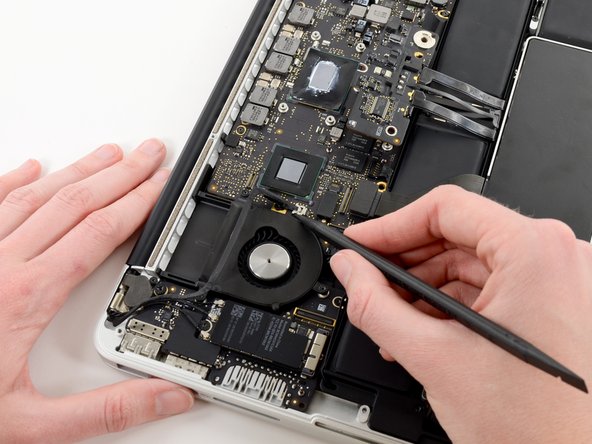
    • Pull the right fan ribbon cable straight out of its socket on the logic board.

  18. MacBook Pro 13" Retina Display Early 2013 Logic Board Replacement: 手順 18、 1の画像 1
    • Remove the three 3.1 mm T5 Torx screws securing the right fan to the logic board assembly.

  19. MacBook Pro 13" Retina Display Early 2013 Logic Board Replacement: 手順 19、 1の画像 1
    • Lift and remove the right fan out of the upper case.

  20. MacBook Pro 13" Retina Display Early 2013 Logic Board Replacement, Left Fan: 手順 20、 2の画像 1 MacBook Pro 13" Retina Display Early 2013 Logic Board Replacement, Left Fan: 手順 20、 2の画像 2
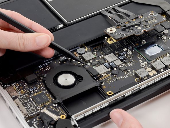
    • Use the tip of a spudger to flip up the retaining flap on the left fan ribbon cable ZIF socket.

    • Be sure you are prying up on the hinged retaining flap, not the socket itself.

  21. MacBook Pro 13" Retina Display Early 2013 Logic Board Replacement: 手順 21、 1の画像 1
    • Remove the three 3.1 mm T5 Torx screws securing the left fan to the logic board assembly.

  22. MacBook Pro 13" Retina Display Early 2013 Logic Board Replacement: 手順 22、 2の画像 1 MacBook Pro 13" Retina Display Early 2013 Logic Board Replacement: 手順 22、 2の画像 2
    • Lift and remove the left fan out of the upper case.

    • Make sure to pull the left fan straight away to simultaneously pull the left fan ribbon cable out of its socket on the logic board.

  23. MacBook Pro 13" Retina Display Early 2013 Logic Board Replacement, Logic Board Assembly: 手順 23、 3の画像 1 MacBook Pro 13" Retina Display Early 2013 Logic Board Replacement, Logic Board Assembly: 手順 23、 3の画像 2 MacBook Pro 13" Retina Display Early 2013 Logic Board Replacement, Logic Board Assembly: 手順 23、 3の画像 3
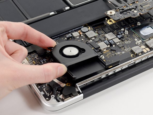
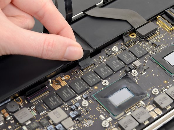
    • Use the tip of a spudger to push the edges of the I/O board connector straight out of its socket on the logic board.

    • It is recommended to carefully push on both sides of the connector to "walk" it out of its socket.

  24. MacBook Pro 13" Retina Display Early 2013 Logic Board Replacement: 手順 24、 2の画像 1 MacBook Pro 13" Retina Display Early 2013 Logic Board Replacement: 手順 24、 2の画像 2
    • Wedge the flat end of a spudger underneath the keyboard backlight connector and the logic board.

    • Gently twist the flat end of a spudger upwards to pry the keyboard backlight connector up off its socket on the logic board.

  25. MacBook Pro 13" Retina Display Early 2013 Logic Board Replacement: 手順 25、 3の画像 1 MacBook Pro 13" Retina Display Early 2013 Logic Board Replacement: 手順 25、 3の画像 2 MacBook Pro 13" Retina Display Early 2013 Logic Board Replacement: 手順 25、 3の画像 3
    • Grab the black pull tab secured to the display data cable lock and rotate it toward the DC-In side of the computer.

    • Pull the display data cable straight out of its socket on the logic board.

    • Do not lift up on the display data cable, as its socket is very fragile. Pull the cable parallel to the face of the logic board.

  26. MacBook Pro 13" Retina Display Early 2013 Logic Board Replacement: 手順 26、 1の画像 1
    • Pry the headphone jack cable connector up off its socket on the logic board.

  27. MacBook Pro 13" Retina Display Early 2013 Logic Board Replacement: 手順 27、 3の画像 1 MacBook Pro 13" Retina Display Early 2013 Logic Board Replacement: 手順 27、 3の画像 2 MacBook Pro 13" Retina Display Early 2013 Logic Board Replacement: 手順 27、 3の画像 3
    • Use the tip of a spudger to flip up the retaining flap on the microphone ribbon cable ZIF socket.

    • Be sure you are prying up on the hinged retaining flap, not the socket itself.

    • Grasp the plastic pull tab and pull the microphone ribbon cable out of its socket.

  28. MacBook Pro 13" Retina Display Early 2013 Logic Board Replacement: 手順 28、 3の画像 1 MacBook Pro 13" Retina Display Early 2013 Logic Board Replacement: 手順 28、 3の画像 2 MacBook Pro 13" Retina Display Early 2013 Logic Board Replacement: 手順 28、 3の画像 3
    • Use the flat edge of a spudger to flip up the retaining flap on the keyboard ribbon cable ZIF socket.

    • Be sure you are prying up on the hinged retaining flap, not the socket itself.

    • Grasp the plastic pull tab and pull the keyboard ribbon cable out of its socket.

  29. MacBook Pro 13" Retina Display Early 2013 Logic Board Replacement: 手順 29、 3の画像 1 MacBook Pro 13" Retina Display Early 2013 Logic Board Replacement: 手順 29、 3の画像 2 MacBook Pro 13" Retina Display Early 2013 Logic Board Replacement: 手順 29、 3の画像 3
    • Repeat the previous procedure to disconnect the Trackpad ribbon cable from its socket on the logic board.

  30. MacBook Pro 13" Retina Display Early 2013 Logic Board Replacement: 手順 30、 2の画像 1 MacBook Pro 13" Retina Display Early 2013 Logic Board Replacement: 手順 30、 2の画像 2
    • Wedge the flat end of a spudger beneath the right speaker cable connector.

    • Gently pry the right speaker cable connector up off from its socket on the logic board.

    • Be sure you are prying up on the connector, not the socket itself.

  31. MacBook Pro 13" Retina Display Early 2013 Logic Board Replacement: 手順 31、 1の画像 1
    • Use the flat end of a spudger to pry the SSD cable connector up off its socket on the logic board.

  32. MacBook Pro 13" Retina Display Early 2013 Logic Board Replacement: 手順 32、 2の画像 1 MacBook Pro 13" Retina Display Early 2013 Logic Board Replacement: 手順 32、 2の画像 2
    • Wedge the tip of a spudger beneath the left speaker cable connector.

    • Gently pry the left speaker cable connector up off from its socket on the logic board.

    • Be sure you are prying up on the connector, not the socket itself.

  33. MacBook Pro 13" Retina Display Early 2013 Logic Board Replacement: 手順 33、 1の画像 1
    • Remove the nine 3.3 mm T5 Torx screws securing the logic board and MagSafe DC-in board to the upper case.

  34. MacBook Pro 13" Retina Display Early 2013 Logic Board Replacement: 手順 34、 2の画像 1 MacBook Pro 13" Retina Display Early 2013 Logic Board Replacement: 手順 34、 2の画像 2
    • Carefully grasp the corner of the logic board (opposite of the I/O ports) and lift the logic board out of the upper case.

  35. MacBook Pro 13" Retina Display Early 2013 Logic Board Replacement, MagSafe DC-In Board: 手順 35、 2の画像 1 MacBook Pro 13" Retina Display Early 2013 Logic Board Replacement, MagSafe DC-In Board: 手順 35、 2の画像 2
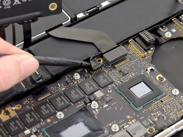
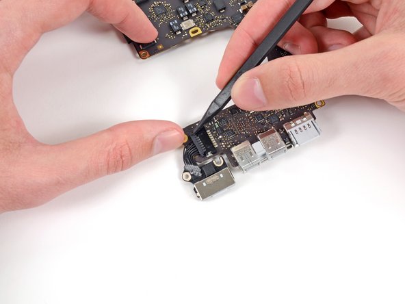
    • Gently push the edges of the MagSafe cable connector away from its socket on the logic board.

    • It is recommended "walk" the connector out of its socket. Simply push the top and bottom corners of the connector and carefully "walk it out" of its socket.

  36. MacBook Pro 13" Retina Display Early 2013 Logic Board Replacement: 手順 36、 1の画像 1
    • Pull the MagSafe cable connector straight out of its socket on the logic board.

  37. MacBook Pro 13" Retina Display Early 2013 Logic Board Replacement, Logic Board: 手順 37、 1の画像 1
    • Logic board remains.

終わりに

To reassemble your device, follow these instructions in reverse order.

14 の人々がこのガイドを完成させました。

作成者

3人の作成者と共同で作成されました。

Sam Goldheart

メンバー登録日: 10/18/12

465,617 ポイント

538のガイドは作成済み

チーム

iFixit iFixit人のメンバー

Staff

135 メンバー

16,732のガイドは作成済み

0 件のコメント

コメントを追加

統計データ:

過去 24時間: 4

過去 7 日: 11

過去 30 日: 53

今までの合計 27,791